
Related Manuals for Generac Power Systems MAGNUM MTT15


Summary of Contents for Generac Power Systems MAGNUM MTT15
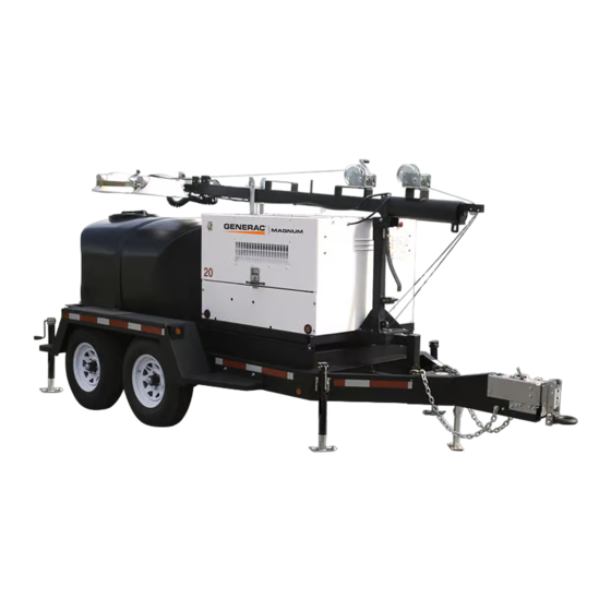
- Page 1 COMBINATION LIGHT TOWER GENERATOR & WATER TRAILER MTT15 • MTT20 • MTT20CAN OPERATING MANUAL 00912 www.discount-equipment.com...
- Page 2 Discount-Equipment.com is your online resource for commercial and industrial quality parts and equipment sales. Locations: Florida (West Palm Beach): 561-964-4949 Outside Florida TOLL FREE: 877-690-3101 Need parts? Check out our website at www.discount-equipment.com Can’t find what you need? Click on this link: http://www.discount-equipment.com/category/5443-parts/ and fill out the request form.
-
Page 3: Introduction
INTRODUCTION This manual provides information and procedures to safely operate and maintain the Magnum Power Products LLC unit. For your own safety and protection from physical injury, carefully read, understand, and observe the safety instructions described in this manual. Keep a copy of this manual with the unit at all times. Magnum Power Products LLC reserves the right to change any portion of this information without notice. -
Page 4: Table Of Contents
TABLE OF CONTENTS Page INTRODUCTION ..........................2 SAFETY NOTES ..........................5 OPERATING SAFETY ........................5 ENGINE SAFETY..........................6 SERVICE SAFETY..........................7 TOWING SAFETY..........................7 REPORTING TRAILER SAFETY DEFECTS ..................8 SAFETY SYMBOL SUMMARY ......................9 SPECIFICATIONS - MTT15 ......................10 SPECIFICATIONS - MTT20 ...................... - Page 5 TRAILER LIGHTS WIRING DIAGRAM - MTT20, MTT20CAN............45 ELECTRIC BRAKES WIRING DIAGRAM - MTT15 ................. 46 SERVICE LOG ..........................47...
-
Page 6: Safety Notes
SAFETY NOTES This is the safety alert symbol. It is used to alert you to potential personal injury hazards. Obey all safety messages that follow this symbol to avoid possible injury or death. This manual contains DANGERS, WARNINGS, CAUTIONS, NOTICES and NOTES which must be followed to prevent the possibility of improper service, damage to the equipment, personal injury or death. -
Page 7: Engine Safety
• If for any reason any part of the mast hangs up or winch cable develops slack while raising or lowering the mast, STOP immediately and contact an authorized service representative. • NEVER remove safety pin or pull mast locking pin while the mast is up. •... -
Page 8: Service Safety
SERVICE SAFETY This unit uses high voltage circuits capable of causing serious injury or death. Only a qualified electrician should troubleshoot or repair electrical problems occurring in this equipment. • Before servicing, make sure the Control Power switch and circuit breakers are in the OFF (O) position, and the negative terminal on the battery is disconnected. -
Page 9: Reporting Trailer Safety Defects
• Towing the unit with water in the tank will adversely affect handling of towing vehicle, specifically maneuvering corners, accelerating, and braking. Ensure operator has experience with towing unit. • Maximum recommended towing speeds for the unit are as follows: With the tank empty, improved road:55 mph (89 km/h) With the tank full, improved road:45 mph (72 km/h) With the tank 1/2 full, improved road:45 mph (72 km/h) -
Page 10: Safety Symbol Summary
SAFETY SYMBOL SUMMARY This equipment has been supplied with numerous safety and operating decals. These decals provide important operating instructions and warn of dangers and hazards. Replace any missing or hard-to-read decals and use care when washing or cleaning the unit. Decal placement and part numbers can be found in the parts manual. Below is a summary of the intended meanings for the symbols used on the decals. -
Page 11: Specifications - Mtt15
SPECIFICATIONS - MTT15 MAGNUM MODEL MTT15 Engine Make/Brand ......................... Mitsubishi Model........................... S4L2-W461ML EPA Tier..........................4f Horsepower - prime hp (kW) ....................23.5 (17.5) Horsepower - standby hp (kW) ..................24.7 (18.4) Operating Speed rpm ......................1800 Displacement in (L) ....................107.40 (1.76) Cylinders - qty........................ -
Page 12: Specifications - Mtt20
SPECIFICATIONS - MTT20 MAGNUM MODEL MTT20 Engine Make/Brand..........................Isuzu Model ...........................4LE1NYGV-03 .............................4LE1NYGV-03E EPA Tier ..........................4i Horsepower - prime hp (kW) ....................32.1 (23.9) Horsepower - standby hp (kW) ...................35.3 (26.3) Operating Speed rpm ......................1800 Displacement in (L) ....................134 (2.2) Cylinders - qty ........................4 Fuel Consumption - 100% prime gph (Lph) ...............1.80 (6.81) Battery Type - Group Number ....................24 Battery Voltage (Quantity per Unit) ..................12V (1) -
Page 13: Specifications - Mtt20Can
SPECIFICATIONS - MTT20CAN MAGNUM MODEL MTT20CAN Engine Make/Brand..........................Isuzu Model ...........................4LE1NYGV-03G EPA Tier ..........................4i Horsepower - prime hp (kW) ....................32.1 (23.9) Horsepower - standby hp (kW) ...................35.3 (26.3) Operating Speed rpm ......................1800 Displacement in (L) ....................134 (2.2) Cylinders - qty ........................4 Fuel Consumption - 100% prime gph (Lph) ...............1.80 (6.81) Battery Type - Group Number ....................24 Battery Voltage (Quantity per Unit) ..................12V (1) -
Page 14: Unit Dimensions
UNIT DIMENSIONS 00217 MTT15, MTT20, 210 in 83 in 31.5 in 86 in MTT20CAN (5.3 m) (2.1 m) (9.6 m) (2.18 m) Specifications are subject to change without notice. -
Page 15: Unit Serial Number Locations
Unit ID Tag Located on inside of front panel Manufactured by Magnum Power Products, LLC., a subsidiary of Generac Power Systems, Inc. (920) 361-4442 (800) 926-9768 Country of Origin Model... -
Page 16: Component Locations
COMPONENT LOCATIONS Mast Rotation Engine Fuel Water Tank Knob Exhaust Fill Cover Control Battery Leveling Jack Leveling Emergency Forklift Jack Stop Switch Pockets LEFT SIDE Engine Radiator Access Access Hose Bibbs Leveling Leveling Jack Jack RIGHT SIDE 00113... -
Page 17: Light Tower Set Up
LIGHT TOWER SET UP 1. For maximum light coverage, locate the unit at ground level or in a spot higher than the area being illuminated by the lamps. WARNING The mast extends up to 31.5 ft (9.6 m). Make sure the area above the unit is open and clear of overhead wires and obstructions. -
Page 18: Raising The Mast
RAISING THE MAST 1. Set up and level the unit. Refer to “Light Tower Set Up” on page WARNING The unit must be leveled before raising the mast. Failure to level the unit will severely reduce the stability and could DETAIL A DETAIL C allow the unit to tip and fall. -
Page 19: Raising The Mast With Electric Winch Option
RAISING THE MAST WITH ELECTRIC WINCH OPTION 1. Set up and level the unit. Refer to “Light Tower Set Up” on page WARNING The unit must be leveled before raising DETAIL C DETAIL D the mast. Failure to level the unit will severely reduce the stability and could allow the unit to tip and fall. -
Page 20: Main Control Panel
MAIN CONTROL PANEL 240VAC MAIN CIRCUIT BREAKER BALLAST INDICATOR LIGHTS HOURS MAST LIGHT SWITCHES GLOW PLUG TURN INDICATOR MAIN GLOW BREAKER PLUGS START NEUTRAL BONDED TO FRAME 00168 1. MAIN CIRCUIT BREAKER: This 240V (100A) breaker will disconnect power to the lights and receptacles. 2. -
Page 21: Emergency Stop Switch
Inspect all electrical cords; repair or replace any that are cut, worn, or bare. Ensure all winch cables are in good condition and centered on each pulley. Do not use if cables are kinked or beginning to unravel. ... -
Page 22: Automatic Shutdown
30 seconds to allow the starter motor to cool and then repeat the starting procedure. Excessive cranking will cause damage to the starter. Note: If oil pressure is not obtained within 15 seconds after the key is switched to the “RUN” position, the low oil automatic shutdown will turn off the fuel supply, stopping the engine. -
Page 23: Voltage Regulation
VOLTAGE REGULATION Units are equipped with an electronic voltage regulator. The voltage regulator controls the output of the generator by regulating the current into the exciter field. The regulator has three screwdriver adjustable potentiometers that may be adjusted for voltage, stability and voltage roll-off (U/F). The voltage regulator is adjusted before shipment from the factory. -
Page 24: Using The Water Supply
4. Turn the Control Power switch to the OFF (O) position. CIRCUIT BREAKERS CONTROL POWER SWITCH GLOW PLUG START 00925 Note: For extended storage time, disconnect the battery. For extended storage requirements, refer to the engine operator’s manual. USING THE WATER SUPPLY CAUTION NEVER use water in the supply tank for human consumption, even if the water is potable. -
Page 25: Lowering The Mast - Manual
3. Fill the tank from a water source. LOWERING THE MAST - MANUAL 1. Shut down the lights and engine, refer to “Shutting Down the Unit” on page 22. Allow the lights to cool 10-15 minutes before lowering the mast. 2. -
Page 26: Removing The Lights For Transportation
4. Release the mast lock by pulling the safety pin on the mast lock and pulling the lock bar free. Lower the mast by holding the lower winch control switch downward until the mast is resting in the transport cradle. Note: If the mast lock bar does not pull free, activate the lower winch slightly to relieve pressure on the mast bar. -
Page 27: Lifting The Unit
10. Maximum recommended speed for highway towing is 45 mph (72 km/h). Recommended off-road towing speed is not to exceed 10 mph (16 km/h) or less, depending on the terrain. LIFTING THE UNIT Do NOT Use To Lift WARNING THE WATER TANK MUST BE EMPTY BEFORE LIFTING THE UNIT. -
Page 28: Basic Maintenance Schedule - Isuzu Engine
○ Coolant is checked visually by inspecting the level in the coolant overflow jug near the radiator. ○ Normal operation is between the full and add markings on the overflow jug, this is known as normal range. ○ WHEN ENGINE IS STOPPED AND COMPLETELY COOL, coolant may be added directly to the jug. •... -
Page 29: Basic Maintenance Schedule - Mitsubishi Engine
BASIC MAINTENANCE SCHEDULE - MITSUBISHI ENGINE Refer to the original equipment manufacturer’s operating manual for a complete list of maintenance requirements. Failure to comply with the procedures as described in the engine operator’s manual will nullify the warranty, decrease performance and cause equipment damage or premature equipment failure. -
Page 30: Winch Use, Operation & Maintenance - Electric
2. Always be sure that the cable and cable attachments are not damaged and are strong enough for the load. Ensure there is an adequate safety factor of at least three times the maximum load for all components used. 3. Referring to the Cable In/Cable Out decal on the winch, turn handle according to the specified direction to lift. -
Page 31: Jack Maintenance
Check Motor Brushes Visually Check Winch And Control MECHANICAL BRAKE The mechanical brake generates heat when loads are lowered and the wire cable is powered out. Care must be taken to avoid overheating the mechanical brake. Whine or chatter associated with a new mechanical brake is normal and typically disappears with use. -
Page 32: Lower Radiator Hose Heater Option - Use And Maintenance
LOWER RADIATOR HOSE HEATER OPTION - USE AND MAINTENANCE CAUTION Improper use of the lower radiator hose heater could result in damage to the engine or personal injury. Do not modify the location of the lower radiator hose heater. The following points should be followed when operating a unit equipped with a lower radiator hose heater. •... -
Page 33: Troubleshooting Automatic Shutdown Conditions
disconnect models, measure across the junction box terminals when the light is unplugged. On hard wired models, remove the mast junction box cover and insert the wire probes into the connector blocks for the light and ground. If proper voltage is not achieved, perform capacitor check to determine if the capacitor or coil needs to be replaced. -
Page 34: Mast Light Connections
MAST LIGHT CONNECTIONS MAST JUNCTION BOX WIRING MAST LIGHT CONNECTIONS 4-LIGHT 4-LIGHT 00175... -
Page 35: Ac Wiring Diagram - Mtt15
AC WIRING DIAGRAM - MTT15 90454_B_06.21.14... -
Page 36: Ac Wiring Diagram - Mtt20, Mtt20Can
AC WIRING DIAGRAM - MTT20, MTT20CAN 90343_ORG_12.14.11... -
Page 37: Ac Wiring Diagram - Receptacle Panel
AC WIRING DIAGRAM - RECEPTACLE PANEL (2x5-20R, 1xTT-30, 1xL14-30R, 2x14-50) 90317_ORG_07.06.11... -
Page 38: Ac Wiring Diagram - Receptacle Panel Options (1 Of 2)
AC WIRING DIAGRAM - RECEPTACLE PANEL OPTIONS (1 OF 2) 30 AMP 30 AMP 50 AMP 50 AMP CIRCUIT CIRCUIT CIRCUIT CIRCUIT BREAKER BREAKER BREAKER BREAKER 20 AMP 20 AMP CIRCUIT CIRCUIT BREAKER BREAKER 240 VOLT 240 VOLT 240 VOLT 240 VOLT 30 AMP 30 AMP... -
Page 39: Ac Wiring Diagram - Receptacle Panel Options (2 Of 2)
AC WIRING DIAGRAM - RECEPTACLE PANEL OPTIONS (2 OF 2) 30 AMP 30 AMP 30 AMP 50 AMP CIRCUIT CIRCUIT CIRCUIT CIRCUIT BREAKER BREAKER BREAKER BREAKER 20 AMP 20 AMP CIRCUIT CIRCUIT BREAKER BREAKER 240 VOLT 240 VOLT 240 VOLT 240 VOLT 30 AMP 30 AMP... -
Page 40: Dc Wiring Diagram - Mtt15
DC WIRING DIAGRAM - MTT15 90322_B_03.07.14... -
Page 41: Dc Wiring Diagram - Mtt20, Mtt20Can
DC WIRING DIAGRAM - MTT20, MTT20CAN 90354_B_05.01.13... -
Page 42: Dc Wiring Diagram - Electric Winch For Mtt15
DC WIRING DIAGRAM - ELECTRIC WINCH FOR MTT15 90443_H_06.10.14... -
Page 43: Dc Wiring Diagram - Electric Winch For Mtt20, Mtt20Can
DC WIRING DIAGRAM - ELECTRIC WINCH FOR MTT20, MTT20CAN 90463_B_07.16.14... -
Page 44: Dc Wiring Diagrams For Options Equipment
DC WIRING DIAGRAMS FOR OPTIONS EQUIPMENT 90323_K_06.04.14... -
Page 45: Trailer Lights Wiring Diagram - Mtt15
TRAILER LIGHTS WIRING DIAGRAM - MTT15 SPADE SPADE 90341_B_12.20.13... - Page 46 TRAILER LIGHTS WIRING DIAGRAM - MTT20, MTT20CAN 90386_A_02.14.14...
- Page 47 ELECTRIC BRAKES WIRING DIAGRAM - MTT15 90286_E_03.18.14...
- Page 48 SERVICE LOG OIL GRADE AND TYPE: ____________________________ BRAND:___________________________________ COOLANT MIXTURE: ______________________________ BRAND:___________________________________ __________________________________________________________________________________________ __________________________________________________________________________________________ __________________________________________________________________________________________ __________________________________________________________________________________________ __________________________________________________________________________________________ __________________________________________________________________________________________ __________________________________________________________________________________________ __________________________________________________________________________________________ __________________________________________________________________________________________ __________________________________________________________________________________________...
- Page 49 www.discount-equipment.com REV: E PART NO: 40125 09.29.14...
Need help?
Do you have a question about the MAGNUM MTT15 and is the answer not in the manual?
Questions and answers