Dimplex LIA 0608HWCF M Installation And Operating Instruction

Dimplex LIA 0608HWCF M Installation And Operating Instruction

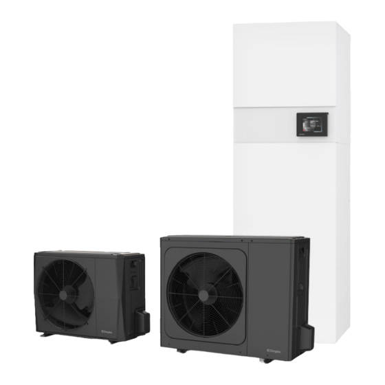
Split air-to-water heat pump with hydrotower compact unit
Table of Contents

Advertisement

Quick Links

LIA 0608HWCF M
LIA 0911HWCF M
Installation and
Operating Instruction
Split air-to-water heat
pump with Hydrotower
compact unit
Order no.: 452172.66.01-EN
LIA 0608 M
LIA 0911 M
Glen
Dimplex
Deutschland
Dimplex
EN · FD 0204

Advertisement

Table of Contents
loading
Need help?

Need help?

Do you have a question about the LIA 0608HWCF M and is the answer not in the manual?

Questions and answers

Summary of Contents for Dimplex LIA 0608HWCF M

  • Page 1 Glen Dimplex Deutschland Dimplex LIA 0608HWCF M LIA 0911HWCF M LIA 0911 M LIA 0608 M Installation and Operating Instruction Split air-to-water heat pump with Hydrotower compact unit Order no.: 452172.66.01-EN EN · FD 0204...
  • Page 3: Table Of Contents

    14 Product information as per Regulation (EU) No 813/2013, Annex II, Table 2 ......EN-31 15 Dimension drawings ..........................EN-33 15.1 Dimension drawing outdoor unit LIA 0608HWCF M ..................EN-33 15.2 Dimension drawing outdoor unit LIA 0911HWCF M ..................EN-34 www.glendimplex.de...
  • Page 4 English LIA 0608HWCF M - LIA 0911HWCF M 15.3 Foundation plan LIA 0608HWCF M........................EN-35 15.4 Foundation plan LIA 0911HWCF M........................EN-35 15.5 Dimension drawing indoor unit ..........................EN-36 16 Diagrams ..............................EN-37 16.1 Operating limits diagram heating ..........................EN-37 16.2 Operating limits diagram cooling ..........................
  • Page 5: Safety Notes

    LIA 0608HWCF M - LIA 0911HWCF M English 1.3 General safety information Safety notes CAUTION! 1.1 Symbols and markings Work on the heat pump must only be performed by authorised and qualified specialist personnel. Particularly important information in these instructions is...
  • Page 6: Intended Use

    English LIA 0608HWCF M - LIA 0911HWCF M 1.4 Intended use Purpose This device is only intended for use as specified by the manu- 2.1 Area of application facturer. Any other use beyond that intended by the manufac- turer is prohibited. This requires the user to abide by the rele- The indoor unit constitutes the interface between a reversible vant project planning documents.
  • Page 7: Scope Of Supply

    LIA 0608HWCF M - LIA 0911HWCF M English Scope of supply 3.1 Indoor unit Cold water inlet Domestic hot water outlet Drain cock Cold water check valve Cleaning flange Return (inlet) Flow (outlet) 12 l expansion vessel Flow meter 10) Touch display...
  • Page 8: Contact Plate

    English LIA 0608HWCF M - LIA 0911HWCF M 3.2 Contact plate 3.3 Heat pump manager The integrated heat pump manager is a convenient electronic CAUTION! regulating and control device. It controls and monitors the en- Before opening the device, ensure that all electric circuits are tire heating system based on the outside temperature, as well disconnected from the power supply.
  • Page 9: Transport And Storage

    LIA 0608HWCF M - LIA 0911HWCF M English A pallet should be used for transportation to the final installa- Transport and storage tion location. During transport and storage, the unit must be kept in a dry Due to the high tare weight of the indoor unit, it should be place and must not be exposed to temperatures below freez- transported by means of a lift truck, hand truck, or similar.
  • Page 10: Installation

    English LIA 0608HWCF M - LIA 0911HWCF M CAUTION! Installation The installation room must meet the requirements for the minimum installation space (see cap. 5.3). 5.1 Indoor unit CAUTION! The unit should always be installed indoors on a level, smooth The device must be installed in a room with sufficient air and horizontal surface.
  • Page 11: Outdoor Unit

    LIA 0608HWCF M - LIA 0911HWCF M English 5.2 Outdoor unit Wall or obstacle  It is advisable to install the outdoor unit close to a wall, on a Air inlet foundation separate from the building with a minimum Maintenance area clearance of 0.3 m on the intake side (Fig.
  • Page 12: Heat Pump Installation Conditions

    English LIA 0608HWCF M - LIA 0911HWCF M 5.3 Heat pump installation 5.2.1 Wall opening for split lines and electric wires conditions: Please proceed as follows when laying split lines and electric The refrigerating system described in this manual is filled with wires: R32.
  • Page 13 LIA 0608HWCF M - LIA 0911HWCF M English 5.3.2 Minimum installation space 5.3.3 Toxicity and flammability limit values: requirements: If the refrigerant fill quantity is below 1.842 kg, the toxicity limit value is the determining factor for the installation conditions.
  • Page 14 English LIA 0608HWCF M - LIA 0911HWCF M 5.3.4 Minimum room volume Calculated according to EN378-1_4:2016 and EN60335-2-40, the following room sizes are obtained (see table) for the respec- tive pipe length and the resulting fill quantity. Due to the flam- mability and toxicity of the refrigerant, the following minimum room sizes must be observed.
  • Page 15: Installation In Coastal Areas

    LIA 0608HWCF M - LIA 0911HWCF M English 5.4 Installation in coastal areas NOTE The use of heat pumps is safe from a distance of 12 km from If the unit is installed close to the sea, the high salt concentra- the sea with a maximum salt content of 3.5%...
  • Page 16: Indoor Unit Installation

    English LIA 0608HWCF M - LIA 0911HWCF M Schritt 1 Unscrew the two screws (1) holding the two sides of Indoor unit installation the upper front panel. Schritt 2 Push front panel A upwards and then pull it out. 6.1 General Schritt 3 Push front panel B upwards and then pull it out.
  • Page 17 LIA 0608HWCF M - LIA 0911HWCF M English Hot water outlet Filling and supplementary water as well as heating water, depending on The hot water outlet connection supplies domestic hot water heat output throughout the building and must be distributed to different Total alkaline earths in mol/m³...
  • Page 18: Connecting The Pipework And Cables To The Outdoor Unit

    English LIA 0608HWCF M - LIA 0911HWCF M CAUTION! Connecting the pipework Only equipment and tools intended for the product, pressure and cables to the outdoor and temperatures may be used for work on the device. unit CAUTION! When working on the device, the use of spark-generating This chapter describes the refrigerant pipe connections and the machines should be avoided.
  • Page 19 LIA 0608HWCF M - LIA 0911HWCF M English 7.1.2 Preparation for pipework Outdoor unit Indoor unit The preparation of the pipework takes place in five steps. One main cause of refrigerant leaks is incorrect flanging. Flanging must be carried out carefully and according to the following steps.
  • Page 20 English LIA 0608HWCF M - LIA 0911HWCF M Step 5: Checks Step 2: Fastening Compare the flanging with the figure. Align the centre of the pipes and tighten the screw nuts by   hand. If the flanging is visibly damaged, cut the relevant section ...
  • Page 21: Electrical Connections

    LIA 0608HWCF M - LIA 0911HWCF M English 7.2 Electrical connections 7.2.2 Indoor component Two supply cables must be connected to the indoor compo- 7.2.1 Outdoor component nent: The power supply for the electric heating element and the control voltage for the integrated heat pump manager. (Load: NOTE 3~;...
  • Page 22: Final Work

    English LIA 0608HWCF M - LIA 0911HWCF M 7.3 Final work Once the pipes and electric cables have been connected, the pipes must be bent and a leak test must be carried out. The leak Seal small gaps around test must be carried out with particular care, as a refrigerant the pipe, e.g.
  • Page 23 LIA 0608HWCF M - LIA 0911HWCF M English 7.4.2 Leakage tightness test 7.4.3 Evacuation Connect the multi-way valve (with pressure gauges) and Connect the end of the filling hose mentioned above to the  dry nitrogen gas cylinder with the filling hoses on this vacuum pump to pump the pipework and indoor unit maintenance connection.
  • Page 24: Commissioning

    English LIA 0608HWCF M - LIA 0911HWCF M Commissioning Heat source Max. temperature spread temperature between heating flow and return 8.1 General from -20 °C -15 °C To ensure that commissioning is performed correctly, it should -14 °C -10 °C only be carried out by an after-sales service technician author- -9 °C...
  • Page 25: Test Points, Maintenance And Troubleshooting

    LIA 0608HWCF M - LIA 0911HWCF M English CAUTION! Test points, maintenance Always wear adequate personal protective equipment and troubleshooting (protective gloves, safety glasses, etc.) when working with refrigerant. If no faults have occurred up to this point, the unit can now be put into operation.
  • Page 26: Maintenance

    English LIA 0608HWCF M - LIA 0911HWCF M 9.2 Maintenance CAUTION! For cleaning and maintenance, especially when removing To maintain an optimal output on the split heat pump, regular covers, the entire system must be disconnected from the checks and maintenance work should be carried out on the power supply beforehand.
  • Page 27: Troubleshooting

    LIA 0608HWCF M - LIA 0911HWCF M English 9.3 Troubleshooting CAUTION! Before opening the device, ensure that all electric circuits are If the split heat pump is experiencing problems during opera- disconnected from the power supply. tion or is not working at all, check the following points.
  • Page 28: Characteristic Curve Temperature Sensor Outdoor Unit

    English LIA 0608HWCF M - LIA 0911HWCF M If the system needs to be completely refilled due to a fault or Evacuate the system and make sure that there is no oxygen leakage, please proceed as follows: or nitrogen in the pipe system.
  • Page 29: Characteristic Curve Temperature Sensor Indoor Unit

    LIA 0608HWCF M - LIA 0911HWCF M English 9.5 Characteristic curve 9.5.2 Mounting the outside temperature sensor temperature sensor indoor unit The outside temperature is measured via the heat source inlet sensor on the outdoor unit. Optionally, a separate outdoor tem- 9.5.1 Sensor characteristic curves...
  • Page 30: Cleaning / Maintenance

    English LIA 0608HWCF M - LIA 0911HWCF M 10.3 Corrosion protection anode 10 Cleaning / maintenance The corrosion protection anode installed in the domestic hot 10.1 Care water cylinder should be electrically checked on a regular basis (at least every two years after commissioning) and be replaced To protect the casing, avoid leaning anything against the device as necessary.
  • Page 31: Device Information

    LIA 0608HWCF M - LIA 0911HWCF M English 13 Device information Type and order code LIA 0608HWCF M LIA 0911HWCF M Design Heat source Version Split Split Controller WPM Touch WPM Touch Thermal energy metering Installation location Indoors/outdoors Indoors/outdoors Performance level...
  • Page 32 English LIA 0608HWCF M - LIA 0911HWCF M Additional model features Type of defrosting Reverse circulation Reverse circulation Frost protection, condensate tray / Yes / Yes Yes / Yes Water in device protected against freezing Max. operating overpressure (heat source/heat sink)
  • Page 33: Product Information As Per Regulation (Eu) No 813/2013, Annex Ii, Table 2

    Regulation (EU) No 813/ 2013, Annex II, Table 2 Information requirements for heat pump space heaters and heat pump combination heaters Model Dimplex LIA 0608HWCF M (LIA 0608 M + LIA HW) Air-to-water heat pump Water-to-water heat pump Brine-to-water heat pump...
  • Page 34 English LIA 0608HWCF M - LIA 0911HWCF M Information requirements for heat pump space heaters and heat pump combination heaters Model Dimplex LIA 0911HWCF M (LIA 0911 M + LIA HW) Air-to-water heat pump Water-to-water heat pump Brine-to-water heat pump...
  • Page 35: Dimension Drawings

    LIA 0608HWCF M - LIA 0911HWCF M English 15 Dimension drawings 15.1 Dimension drawing outdoor unit LIA 0608HWCF M 1008 www.glendimplex.de 452172.66.01-EN · FD 0204 EN-33...
  • Page 36: Dimension Drawing Outdoor Unit Lia 0911Hwcf M

    English LIA 0608HWCF M - LIA 0911HWCF M 15.2 Dimension drawing outdoor unit LIA 0911HWCF M 1118 EN-34 452172.66.01-EN · FD 0204 www.glendimplex.de...
  • Page 37: Foundation Plan Lia 0608Hwcf M

    LIA 0608HWCF M - LIA 0911HWCF M English 15.3 Foundation plan LIA 0608HWCF M Foundation > 80 ca. 1000 15.4 Foundation plan LIA 0911HWCF M Foundation > 80 ca. 1110 www.glendimplex.de 452172.66.01-EN · FD 0204 EN-35...
  • Page 38: Dimension Drawing Indoor Unit

    English LIA 0608HWCF M - LIA 0911HWCF M 15.5 Dimension drawing indoor unit EN-36 452172.66.01-EN · FD 0204 www.glendimplex.de...
  • Page 39: Diagrams

    LIA 0608HWCF M - LIA 0911HWCF M English 16 Diagrams 16.1 Operating limits diagram heating Heat source inlet temperature [°C] www.glendimplex.de 452172.66.01-EN · FD 0204 EN-37...
  • Page 40: Operating Limits Diagram Cooling

    English LIA 0608HWCF M - LIA 0911HWCF M 16.2 Operating limits diagram cooling Heatsink inlet temperature [°C] EN-38 452172.66.01-EN · FD 0204 www.glendimplex.de...
  • Page 41: Circuit Diagrams

    LIA 0608HWCF M - LIA 0911HWCF M English 17 Circuit diagrams 17.1 Circuit diagram 6 kW / 10 kW FACTORY S6-1 S6-2 S6-3 SETTINGS 6 KW 1 2 3 10 KW blue 1 2 3 black PCB A, Inverter board...
  • Page 42: Legend

    English LIA 0608HWCF M - LIA 0911HWCF M 17.2 Legend PCB A, inverter board for 1-phase Connection for fan CN19 Output connection for +12V/9V CN20 Connection for communication with PCB B CN32 CN501 Input connection L for the rectifier bridge...
  • Page 43: Hydraulic Integration Diagrams

    LIA 0608HWCF M - LIA 0911HWCF M English 18 Hydraulic integration diagrams 18.1 Mono energy system with one heating circuit and domestic hot water preparation NOTE The hydraulic integration diagram is an example and intended only as an aid. The system requires professional and safety- approved layout by a specialist planner.
  • Page 44: Mono Energy System With Two Heating Circuits And Domestic Hot Water Preparation

    English LIA 0608HWCF M - LIA 0911HWCF M 18.2 Mono energy system with two heating circuits and domestic hot water preparation NOTE The hydraulic integration diagram is an example and intended only as an aid. The system requires professional and safety- approved layout by a specialist planner.
  • Page 45: Legend

    LIA 0608HWCF M - LIA 0911HWCF M English 18.3 Legend Isolating valve Overflow valve Check valve Circulating pump Room-temperature controlled valve Isolating valve with check valve Heat consumer Temperature sensor Three-way mixer Pressure reducer Outdoor unit Indoor unit Buffer tank...
  • Page 46: Declaration Of Conformity

    English LIA 0608HWCF M - LIA 0911HWCF M 19 Declaration of conformity You can find the current CE declaration of conformity to download. EN-44 452172.66.01-EN · FD 0204 www.glendimplex.de...
  • Page 47 LIA 0608HWCF M - LIA 0911HWCF M English www.glendimplex.de 452172.66.01-EN · FD 0204 EN-45...
  • Page 48 Glen Dimplex Deutschland Service and technical support Head office After-sales service, technical support Glen Dimplex Deutschland GmbH and spare parts Am Goldenen Feld 18 Assistance before and after installation D-95326 Kulmbach of your equipment T +49 9221 709-100 T +49 9221 709-545...

This manual is also suitable for:

Lia 0911hwcf mLia 0911 mLia 0608 m

Table of Contents