Table of Contents
Advertisement
Please note that some of the contact details on
this PDF document may not be current.
Please use the following details if you need to
Email: customer.services@gdcgroup.co.uk
The customer support section of our website also features a wide
range of information which may be of use to you and is available
24 hours a day. It includes:
• Operating and installation instructions
• Easy 'How to use' guides for storage heaters
• Service and repairs
• Where to buy our products
• Literature downloads
• Heating requirement calculator
Visit ‐ www.dimplex.co.uk/support
A division of GDC Group Ltd
Millbrook House Grange Drive Hedge End Southampton SO30 2DF
www.dimplex.co.uk
Contact Details
contact us:
Telephone: 0844 879 3588
Registered No: 1313016 England
VAT GB 287 1315 50004
EEE Producer Registration Number –
WEE/ GE0057TS
Paper from sustainable sources
Advertisement
Table of Contents

Related Manuals for Dimplex LA 6 MI


Summary of Contents for Dimplex LA 6 MI
- Page 1 • Easy ‘How to use’ guides for storage heaters • Service and repairs • Where to buy our products • Literature downloads • Heating requirement calculator Visit ‐ www.dimplex.co.uk/support A division of GDC Group Ltd Registered No: 1313016 England VAT GB 287 1315 50004 Millbrook House Grange Drive Hedge End Southampton SO30 2DF EEE Producer Registration Number –...
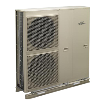
- Page 2 LA 6 MI LA 9 MI LA 12 MI LA 16 MI Technical planning manual Inverter air to water heat pump for outdoor installation 08/60393/0...
-
Page 3: Supporting Documents
Horstmann wall mounted room thermostat The installation of an Air-eau heat pump should only be carried out by a suitably trained and competent person who is approved by Dimplex. All installations should be in accordance with this planning manual to ensure efficient operation. -
Page 4: Table Of Contents
Section 5: DHW preparation with inverter heat pumps ......................13 Dimplex EC-Eau cylinder range ............................13 Dimplex ECS Combination DHW and Buffer Cylinders ...................... 13 Heat pump power for hot water preparation ........................13 Selecting a DHW cylinder ..............................13 Cylinder volume and reheat .............................. - Page 5 Minimum maintenance clearances ............................. 17 Sound insulation measures ..............................17 Air quality .................................... 18 Local planning regulation..............................18 MCS Planning Standard ..............................18 Town and Country planning, England ..........................18 Planning in Wales and Northern Ireland ..........................19 Town and Country planning, Scotland ..........................20 Section 7: Heating System Connection ..........................
- Page 6 LA 12 MI performance ................................ 44 LA 16 MI performance ................................ 46 Product Dimensions LA 6 MI and LA 9 MI .......................... 48 Product Dimensions LA 12 MI and LA 16 MI ........................49 LA 6 MI and LA 9 MI Spare parts ............................50 LA 12 MI and LA 16 MI Spare parts ...........................
-
Page 7: Section 1: Introduction
If demand increases the fixed speed This device is only intended for use as specified by Dimplex as detailed within this technical manual. The air- compressor will be on more often. to-water heat pump is to be used exclusively for the Even though an inverter compressor cycles less, to ensure heating of heating water in a closed circuit. -
Page 8: Advantages Of Fixed Speed Compressors
The fixed speed The product code for the inverter range of heat pumps continues the same convention as the rest of Dimplex‟s compressor has a larger starting current because it doesn‟t turn on gradually. The starting current is smoothed heat pump range. -
Page 9: Section 2: Selection And Sizing Of The Heat Pump
Factor that electricity is used to supplement the heat load. Integration of another boiler such as gas, oil or LPG is not possible with the LA MI but is possible with Dimplex‟s WPM range. Accurately determining the building’s heat loss It is essential to accurately calculate the buildings heat loss to ensure the heat pump is correctly sized. -
Page 10: Estimating The Building"S Heat Loss
Dimplex design service Dimplex offer a free of charge service to calculate a Typical room Ventilation temperatures changes factor buildings heat loss along with a full product and accessory per hour specification. Providing we receive the information below, turnaround is usually 7-10 working days. -
Page 11: Sizing Example 1
Figure 1: Example heat output curves to EN14511 heat loss of 5.0kW at a design temperature of -1.8C and a the for the LA 6 MI for a heat loss of 4.5kW at a design building heat loading being met down to -15C. -
Page 12: Section 3: System Controls In A Domestic Setting
Section 3: System controls in a domestic setting Boiler inter lock of 15C, the ThermoPlus aims to provide maximum comfort to the user and prevent hypothermia and keep a The Domestic heating compliance guide sets out the best level of background heat. Under the flap the blue standby button will put the control into „frost protection‟... -
Page 13: Section 4: Selection Of Heat Emitters And Flow Temperatures
Hard copies are available upon request by contacting the shown in Figure 5. The full guide is available for download MarComs team at Dimplex. from HHIC website. The guide shows that systems with lower flow temperature achieve the highest SPF‟s which would reduce running costs and carbon emissions. -
Page 14: Section 5: Dhw Preparation With Inverter Heat Pumps
If a different cylinder temperature is required the to the cylinder/ambient air. following must be taken into account. For each of Dimplex‟s heat pump cylinders, a graph of kW input vs Page 13... -
Page 15: Cylinder Volume And Reheat
ECS150HP-580 Heat Pump Cylinder model with correct flow rate ECS175HP-580 ECS125HP-580 ECS210HP-580 ECS150HP-580 ECS250HP-580 ECS175HP-580 LA 6 MI ECS300HP-580 (Flow rate 1.0m ECS210HP-580 Table 9: Calculated cylinder reheat time with different heat ECS250HP-580 pumps ECS300HP-580 Cylinder replacement ECS125HP-580 ECS150HP-580 If a heat pump is being installed on to an... -
Page 16: Sterilisation
55ºC for a short period of time. For private domestic properties, Dimplex recommend that the cylinder is raised to 60°C once per week It is therefore, not uncommon for the LA MI to achieve... -
Page 17: Section 6: Installation Considerations
Suggested dimensions of concrete pads as shown in items contained within this chapter should be considered. The installation of an air source heat pump should be carried out by a Dimplex Accredited installer. Physical location The heat pump is for outdoor installation only. It should also be installed in a place where: ... -
Page 18: Ventilation
Figure 7: Top view of two concrete mounting blocks that allow the condensate to drain away via a gravel soak away. Ventilation The installation site must be an open location clear of any obstacles which may cause a short circuiting of the discharged air or increased resistance due to blocking of the inlet or outlet. -
Page 19: Air Quality
LA 16 MI 64.0dB(A) evaporator. Dimplex offer an extra service to coat the Table 10: Minimum distances to achieve 42dB if there is a evaporator with a protective coating. This additional wall between the heat pump and assessment position service adds a week to the delivery times. -
Page 20: Planning In Wales And Northern Ireland
Heat pump will be within 1m of the property boundary. Heat pump is installed on a pitched roof or 1m from the edge of a flat roof. Proposed site is a scheduled monument, listed building, conservation area or world heritage ... -
Page 21: Town And Country Planning, Scotland
Town and Country planning, Scotland A domestic installation of an air source heat pump in Scotland will be classed as a Permitted Development, unless: It would result in the presence within the curtilage of a dwelling of more than one air source heat pump ... -
Page 22: Section 7: Heating System Connection
The installation of an air source heat pump Failure to observe the minimum water throughput will must be carried out by a Dimplex Qualified cause the heat pump not to work due to operation of installer. the flow switch alarm (H62). -
Page 23: Plumbing Connections
Model Fitting size Torque rain water to ensure that large quantities of water can be drained off. LA 6 MI 1 ¼” male flat face LA 9 MI 118 Nm The condensate must drain on to an surface that is freely draining. It must not drain on to... -
Page 24: Filter
Filter It is essential to install a filter immediately before the water inlet to the heat pump. Not installing this filter would invalidate the warranty of the heat pump as debris can easily block the condenser channels. The MFK114 isolation valve as shown in Figure 14 is included in the heat pump packages. -
Page 25: Port Valves
The contacts on the high limit stat will remain closed during LA 6 MI normal operation. If the heat pump does not detect continuity across both the regulation stat and high limit Table 13: Size of expansion vessel in the LA MI range stat an H91 error will occur. -
Page 26: Section 8: Electrical Connection
Section 8: Electrical Connection Depending upon the installation the heat pump could When connecting the heat pump to have the following cables that it will be necessary to the power supply, the relevant EN route from the heat pump into the property. standards must be complied with. -
Page 27: Connection Of The Power Supply To The Heat Pump
Connection of the power supply to the Heat pump LA 6 and 9 MI LA 12 and 16 MI Figure 21: Connection of the power supply cable Main power supply cable The power connection of the heat pump is made via a standard 3-core cable. - Page 28 DHW immersion switched DHW immersion switched by heat pump by a relay controlled by the heat pump or no DHW immersion installed LA 6 MI LA 9 MI RCCD 1 RCCD 2...
-
Page 29: Inline Flow Boiler
Inline flow boiler 2. Using an insulated tool to gently push the centre button on the OLP. 3. Replace the OLP cover. If the inline flow boiler is not wired in the frost protection function will not fully function. The circulation pump will run but no additional heat will be added to Domestic hot water immersion the system by the inline flow boiler. -
Page 30: Controller Cable
Controller cable The controller cable is connected to the heat pump controller using the two rectangular plug connectors as shown in Figure 24. The cable cannot be extended because this would increase the resistance and correct operation controller cannot guaranteed. The cable is 15m long but 1.5m is required inside the heat pump leaving 13.5m for Figure 26: Terminals of the extension lead and 15m routing to the controller. -
Page 31: Connection With The System
Connection with the system The following section contains general information about the communication connections. Full wiring diagrams and hydraulics for standard systems are available in Section 16. Figure 27: Heat pump communication connections This can be used to remotely put the heat pump in standby mode upon breaking the connection from an external control device. -
Page 32: Section 9: System Health Checks
Pressure relief valve operation is normal. Section 10: Standard packages To assist with the design and installation of a system Dimplex have collated wiring and hydraulic schematics for the following designs: Package 1 and 2 Heating and Domestic hot water preparation is done Package 3 ... - Page 33 1 heating zone and DHW with combined buffer and DHW cylinder with separate buffer and 1 heating zone with buffer DHW cylinder tank LA 6 MI LA 9 MI LA 12 MI LA 16 MI PRT1 wall thermostat NTC 2 DHW sensor...
- Page 34 An expansion internal vessel is supplied, an addition one may be Expansion vessel required depending upon system volume. Filling point / Drain down point Bypass for heating circuit Heat emitters Table 16: Components not supplied by Dimplex but required to complete the installation. Page 33...
-
Page 35: Package 1 And 2 - Plumbing Schematic
Package 1 and 2 – Plumbing Schematic Page 34... -
Page 37: Section 11: Technical Specification Of The La Mi Range
Section 11: Technical specification of the LA MI range Component Notes Water Pump Circulates water around the heating circuit. Pressure Gauge Gives the pressure of the water in the heating circuit. Flow Switch Checks the water flow in the heating circuit for efficient and safe operation. Pressure relief valve A safety device that relieves the pressure in the heating circuit if it exceeds 3 bar. -
Page 38: Approvals
Approvals LA 6 MI LA 9 MI LA 12 MI LA 16 MI MCS certificate number HP0017/24 HP0017/25 HP0012/20 HP0012/21 MCM identifier (SAP Appendix Q) LA 6 MI LA 9 MI LA 12 MI LA 16 MI Performance Data Type and order code... -
Page 39: Performance Data
Performance Data Type and order code LA 12 MI LA 16 MI Design Degree of protection according to EN 60 529 for a compact unit or heating element IP 24 IP 24 Installation location Outdoors Outdoors Performance Data Operating temperature limits: Heating water flow / return flow °C Max. -
Page 40: Ce Declaration Of Conformity
CE declaration of conformity Page 39... -
Page 41: La 6 Mi Performance
LA 6 MI performance Page 40... - Page 42 LA 6 MI (continued) Page 41...
-
Page 43: La 9 Mi Performance
LA 9 MI performance Page 42... -
Page 44: La 9 Mi Performance (Continued)
LA 9 MI performance (continued) Page 43... -
Page 45: La 12 Mi Performance
LA 12 MI performance Page 44... - Page 46 LA 12 MI performance (continued) Page 45...
-
Page 47: La 16 Mi Performance
LA 16 MI performance Page 46... - Page 48 LA 16 MI performance (continued) Page 47...
-
Page 49: Product Dimensions La 6 Mi And La 9 Mi
Product Dimensions LA 6 MI and LA 9 MI Page 48... -
Page 50: Product Dimensions La 12 Mi And La 16 Mi
Product Dimensions LA 12 MI and LA 16 MI Page 49... -
Page 51: La 6 Mi And La 9 Mi Spare Parts
LA 6 MI and LA 9 MI Spare parts Note, the non-numbered parts are not kept as standard service parts. Page 50... - Page 52 LA 6 MI and LA 9 MI Spare parts (continued) Note, the non-numbered parts are not kept as standard service parts. Page 51...
- Page 53 LA 6 MI and LA 9 MI Spare parts (continued) Note, the non-numbered parts are not kept as standard service parts. Page 52...
- Page 54 LA 6 MI and LA 9 MI Spare parts (continued) Note, the non-numbered parts are not kept as standard service parts. Page 53...
- Page 55 LA 6 MI and LA 9 MI Spare parts (continued) Note, the non-numbered parts are not kept as standard service parts. Page 54...
-
Page 56: La 12 Mi And La 16 Mi Spare Parts
LA 12 MI and LA 16 MI Spare parts Note, the non-numbered parts are not kept as standard service parts. Page 55... - Page 57 LA 12 MI and LA 16 MI Spare parts (continued) Note, the non-numbered parts are not kept as standard service parts. Page 56...
- Page 58 LA 12 MI and LA 16 MI Spare parts (continued) Note, the non-numbered parts are not kept as standard service parts. Page 57...
- Page 59 LA 12 MI and LA 16 MI Spare parts (continued) Note, the non-numbered parts are not kept as standard service parts. Page 58...
- Page 60 LA 12 MI and LA 16 MI Spare parts (continued) Note, the non-numbered parts are not kept as standard service parts. Page 59...
-
Page 61: Information For Dhw Cylinder With Buffer - Ecs125Hp-580
Information for DHW cylinder with buffer - ECS125HP-580 Page 60... -
Page 62: Information For Dhw Cylinder With Buffer - Ecs150Hp/75-580
Information for DHW cylinder with buffer - ECS150HP/75-580 Page 61... -
Page 63: Information For Dhw Cylinder With Buffer - Ecs210Hp/75-580
Information for DHW cylinder with buffer - ECS210HP/75-580 Page 62...
Need help?
Do you have a question about the LA 6 MI and is the answer not in the manual?
Questions and answers