Honeywell PRO-2200 Installation Manual
Hide thumbs
Also See for PRO-2200:
- Installation manual (16 pages) ,
- Installation manual (16 pages) ,
- Installation manual (15 pages)

Related Manuals for Honeywell PRO-2200


Summary of Contents for Honeywell PRO-2200
- Page 1 PRO-2200 Output Module Installation Manual Part Number: PRO22OUT A division of Northern Computers, Inc. TD1142 rev0501...
-
Page 3: Table Of Contents
PRO-2200 Output Module PRO22OUT Installation Guide Contents Warnings and Cautions ..................4 Disclaimer ......................6 Product Liability; Mutual Indemnification ..............6 Unpacking Procedure ................... 6 Shipping Instructions .................... 7 Limited Warranty ....................7 Confidentiality ..................... 8 Description ......................9 Set Up ....................... 9 LED Operation .................... -
Page 4: Warnings And Cautions
Always make certain that any required approvals are obtained in writing. DO NOT ACCEPT VERBAL APPROVALS, THEY ARE NOT VALID. Engineered Systems never recommends using the PRO-2200 or related products as a primary warning or monitoring system. Primary warning or monitoring systems should always meet local fire and safety code requirements. - Page 5 PRO-2200 Output Module PRO22OUT Installation Guide CAUTION IF ANY DAMAGE TO THE SHIPMENT IS NOTICED, A CLAIM MUST BE FILED WITH THE COMMERCIAL CARRIER RESPONSIBLE. CAUTION Electro-static discharge can damage CMOS integrated circuits and modules. To prevent damage always follow these procedures: Use static shield packaging and containers to transport all electronic components, including completed reader assemblies.
-
Page 6: Disclaimer
PRO-2200 Output Module PRO22OUT Installation Guide Disclaimer Product Liability; Mutual Indemnification In the event that a Customer receives a claim that a Product or any component thereof has caused personal injury or damage to property of others, Customer shall immediately notify Engineering Systems in writing of all such claims. -
Page 7: Shipping Instructions
PRO-2200 Output Module PRO22OUT Installation Guide Shipping Instructions To ship equipment back to Engineering Systems: 1. Contact the customer service department at 800-323-4576, before returning equipment. Before calling, please have available: • A description of the problem or reason for returning the equipment. -
Page 8: Confidentiality
PRO-2200 Output Module PRO22OUT Installation Guide Confidentiality All software, drawings, diagrams, specifications, catalogs, literature, manuals and other materials furnished by Engineering Systems relating to the design, use and service of the Products shall remain confidential and shall constitute proprietary rights of Engineering Systems and Customer agrees to treat such information as confidential. -
Page 9: Description
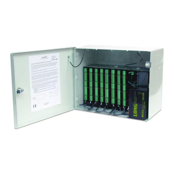
PRO-2200 Output Module PRO22OUT Installation Guide Description The Output Board provides connections for 16 relay outputs. This board can be rack mounted, in which case, only one edge is accessible for wiring. Mounting the board flat increases the amount of available I/O slightly but also significantly decreases the number of boards that can be mounted in one enclosure. - Page 10 PRO-2200 Output Module PRO22OUT Installation Guide Dipswitch Settings: * = Default...
-
Page 11: Led Operation
PRO-2200 Output Module PRO22OUT Installation Guide LED Operation The Output board uses two on-board LEDs to provide status information during its power- up sequence and normal operation. n i t n i t n i t i t i i l a... -
Page 12: Alarm Contact Wiring
PRO-2200 Output Module PRO22OUT Installation Guide For Wiring to an RS-485 port: 1. TR+ is the plus side of the transmit and receive differential signal 2. TR– is the negative side of the transmit and receive differential signal. 3. GND is the signal ground. The wiring for this signal is required and NOT optional. -
Page 13: Mounting Options
PRO-2200 Output Module PRO22OUT Installation Guide protection circuit as close to the load as possible (within 12 inches [30cm]). The effectiveness of the circuit decreases as the distance from the load increases. Relays 13 through 16 are general purpose relay outputs and are not available when the board is rack mounted. -
Page 14: Specification
PRO-2200 Output Module PRO22OUT Installation Guide Specification The Output board is for use in low voltage, class 2 circuits only. Primary power: 12 VDC±10% 400mA Relay contacts: Relays 1 through 16 outputs, Form-C, 2A @ 28 VDC, resistive Inputs: Two unsupervised dedicated inputs... -
Page 15: Wiring Diagram For Connectors 1 Through 8
PRO-2200 Output Module PRO22OUT Installation Guide Wiring Diagram for Connectors 1 through 8... -
Page 16: Wiring Diagram For Connectors 7 Through 11
PRO-2200 Output Module PRO22OUT Installation Guide Wiring Diagram for Connectors 7 through 11 16 OUTPUT Tamper Switch (In Close Position BOARD when Cabinet Door Is Closed) +12VDC Power Supply Tamper Switch Common C - No Charging Power Fail N/C - No Charging... -
Page 17: Notes
PRO-2200 Output Module PRO22OUT Installation Guide NOTES... - Page 18 PRO-2200 Output Module PRO22OUT Installation Guide NOTES...
- Page 20 Honeywell Security & Data Collection 2700 Blankenbaker Pkwy, Suite 150 Louisville, KY 40299 (800) 675-3364 www.honeywellaccess.com...
Need help?
Do you have a question about the PRO-2200 and is the answer not in the manual?
Questions and answers