Table of Contents
Advertisement
Quick Links
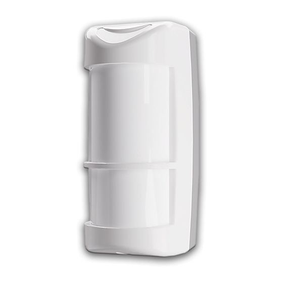
JA-169P outdoor dual PIR motion detector
This detector is a component of the JABLOTRON system. The JA-169P
dual wireless outdoor intruder detector is designed to detect human body
movement in an outdoor environment. The detector consists of JL01
detector produced by LINCE Italia S.r.l., and a JA-150TX-V1 transmitter
produced by JABLOTRON ALARMS. The optical part of the detector has
2 PIR sensors (dual zone detection) and a high immunity to false alarms and
detection of small animals. The detector is equipped with one tamper contact.
Tamper contact immediately reports any attempt on opening the detector or
demount from mounting place.
The detector should be installed by a trained technician with a valid
certificate issued by an authorised distributor.
Installation
Conditions:
1.
The detector has to be installed onto a vertical wall (in a position
where its bottom surface is parallel to the guarded zone).
2.
The detector should be installed 1–1.2 m above the ground.
3.
The best movement detection is provided when the detection beams
intersect.
4.
No other objects capable of causing detection interference (bushes,
trees, high grass, air-conditioners, etc.) should be situated in the field of
view of the detector.
5.
Avoid direct effects of strong sources of light (sun reflections, etc.).
Procedure:
1. Unscrew the locking screw (1) on the bottom of the upper cover of
the detector and remove the detection part's cover (3).
2. Unscrew seven screws which hold the detector´s main board (5) and
pull it out by tilting as you pull it out. There is a radio transmitter fitted
onto the rear side of the detector´s PCB.
3. Unscrew the 4 screws which link the rear cover (7) with the mounting
plate.
4. The detector can be mounted onto a level mounting place by the 4
screws through the mounting plate. Or it can be mounted on a pole
by metal ties (not supplied).
Warning: Do not touch the detector sensors
In case that physical contact does occur, it´s
necessary to clean the sensor with the use of
a cotton swab dipped in rubbing alcohol.
Fig. 1.: 1 – bracket screws, 2 – locking screw, 3 – front cover,
4 –adjustment knob for lower PIR (PIR2), 5 – PCB holder, 6 – tamper
contact 7 – mounting backplate
Enrolling the detector to the system
Signal transmitter for wireless communication is located underneath
the main board part of the detector. The battery is inserted into
the battery holder placed on the transmitter's PCB.
JA-169P
during handling
Enrolment procedure to the system:
a. In the F-Link software, select the required position in the Devices
window and launch the enrolment mode by clicking on the "Enrol"
option.
b. Insert the batteries (mind the correct polarity). When the first battery
has been inserted into the battery holder an enrolment signal is
transmitted to the control panel and the detector is enrolled to the
selected position.
c. Assemble the detector in opposite order in which it was
disassembled.
Fig. 2 – Transmitter JA-150TX-VXI: 1 – wire terminals, 2 – settings DIP
switch (pre-set from factory, see picture), 3 – external tamper contact
jumper, 4 – battery holder, 5 – external antenna jumper,
6 – external antenna connector
Notes:
−
There must be a JA-11xR radio module installed in the control
panel.
−
The detector can also be enrolled into the system by entering its
serial number (7) in the F-Link software. You can find the serial
number on the sticker, glued onto the PCB. All numbers under
the bar code has to be entered (1400-00-0000-0001).
−
If needed the transmitter can be equipped with an AN-868 (2PIN)
external antenna connected to the connector (6) and disconnect
the jumper (5).
−
For a DIP switch change of settings, the detector has to be
completely turned off.
Normal operation mode
The detector sends an activation radio signal when it is triggered.
In the case of tampering with the detector or tearing the detectoroff its
location, the detector sends a tamper signal. A status report is sent every
9 minutes to the control panel.
Checking and replacing the batteries
The detector checks the battery status automatically. Nearly drained
battery is reported by continuous flashing of yellow signalling LED on
the detector (1 flash per sec) and at the same time low battery status is
reported to the control panel. The detector remains fully functional.
The battery should be replaced as soon as possible.
The control panel must be in service mode before battery
replacement (see the control panel installation manual). Tamper
contact must be pressed several times after opening the cover and
removing the battery to discharge capacitors.
Setting up the optical part
of the detector
The optical part of the detector includes 2 PIR sensors with an optional
AND logic. They detect movement in two planes. The detecting angle of
the lower PIR sensor can be adjusted. The alarm signal is triggered only
if both detecting planes are triggered at the same time if the detector is
configured in such a way.
1/2
MMY57100
Advertisement
Table of Contents

Related Manuals for jablotron JA-169P


Summary of Contents for jablotron JA-169P
- Page 1 JA-169P outdoor dual PIR motion detector Enrolment procedure to the system: This detector is a component of the JABLOTRON system. The JA-169P dual wireless outdoor intruder detector is designed to detect human body a. In the F-Link software, select the required position in the Devices movement in an outdoor environment.
- Page 2 This must be taken into consideration during the JA-169P detector is in a compliance with the relevant detection range adjustment. Union harmonisation legislation: Directives No: 2014/53/EU, The detection area angle is 85°. Direction of the detection angle can 2014/35/EU, 2014/30/EU, 2011/65/EU.
Need help?
Do you have a question about the JA-169P and is the answer not in the manual?
Questions and answers