
Subscribe to Our Youtube Channel
Related Manuals for Svantek SV 111


Summary of Contents for Svantek SV 111
- Page 1 SV111 User Manual USER MANUAL SV 111 Warsaw, 2018-12-19 Copyright © 2018 SVANTEK. Rev. 01.02 All rights reserved.
- Page 2 Information in this document is subject to change without notice and does not represent a commitment on the part of Svantek. Svantek provides this document “as is”, without warranty of any kind, either expressed or implied, including, but not limited to, its particular purpose. Svantek reserves the right to make improvements and/or changes to this manual, or to the products and/or the programs described in this manual, at any time.
-
Page 3: Table Of Contents
SV111 User Manual CONTENTS General safety summary ......................... 4 Calibration ............................5 Accuracy of calibration ........................5 SV111 model information ....................... 5 Unpacking and Inspecting the package contents ................6 Optional accessories ........................7 SV111 vibration calibrator ....................... 8 Control panel ........................... 9 Operating diagram ........................ -
Page 4: General Safety Summary
SV111 User Manual 1. General safety summary Review the following safety precautions to avoid injury and prevent from damaging this product or other products connected with it. To avoid potential hazards, use this product only as specified. Qualified personnel should only perform the service procedures. -
Page 5: Calibration
SV111 User Manual 2. Calibration One of the fundamental questions, that are most frequently asked while taking a measurement, is whether its result is accurate. Proceeding, with a measurement without having a positive answer to this question, may result in obtaining data of no practical use and wasting our time. -
Page 6: Unpacking And Inspecting The Package Contents
(if ordered). In case of any problems, please contact an authorized Svantek representative, the service staff or the manufacturer directly. The complete set includes the following items: ... -
Page 7: Optional Accessories
SV111 User Manual Charge SV111 to the full. In order to charge the battery, connect SA33 AC/DC adapter plug to SV111 EXT_DC supply socket and then connect it to the mains. SA33 AC/DC adapter is placed in the charger slot. ... -
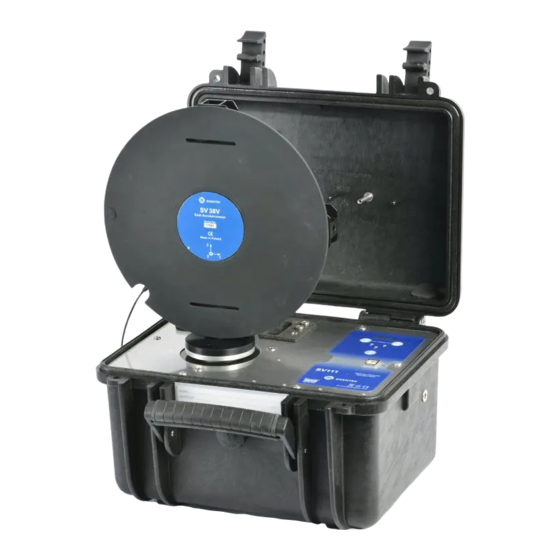
Page 8: Sv111 Vibration Calibrator
SV111 User Manual 7. SV111 vibration calibrator SV111 vibration calibrator 1.Magnet with two screwdriver tips; 2.Adapter; 3.Hex wrench slot with support sleeves; 4.Charger slot; 5.Shaker; 6.Transportation lock; 7.Support; 8. astening screw; 9.Display; 10.Keyboard; 11.EXT_DC supply socket; 12.USB port;... -
Page 9: Control Panel
SV111 User Manual 8. Control panel SV111 control panel 1.Vibrations level button/Power on button A; 2.Start/Stop button; 3.Serial number box; 4.Display box; 5.Vibration frequency button/Power button B; 6. Spirit level; 7.USB port... -
Page 10: Operating Diagram
SV111 User Manual 9. Operating diagram Sensor installation SV 111 switching on SV 111 levelling SV 111 levelled Skipping the levelling Vibration parameters setting … menu Sample vibration Start shaker Vibrations Shaker vibrates parameters not Shaker with set reached properly... -
Page 11: Submenu Diagram
SV111 User Manual 10. Submenu diagram Program submenu can be reached from “Vibrations parameters setting menu” by pressing To return to “Vibrations parameters setting menu” press... -
Page 12: Installation Of The Whole-Body Sensor
SV111 User Manual 11. Installation of the whole-body sensor The whole-body sensor can be tested/calibrated at 15.92 Hz only! dismantle the adapter from the case cover and screw it to the shaker with one or more bolts (one central bolt should be sufficient for the system check) ... - Page 13 SV111 User Manual position the sensor according to the calibrated axis (channel) and tight the fixing bolt: put the support system with the tested sensor in the horizontal position on the adapter and tight the fixing bolt:...
-
Page 14: Installation Of The Sv 105 Hand-Arm Sensor
In case the fixing screws are lost, please contact your local distributor or send an e-mail to office@svantek.com. To avoid malfunction of the sensor during in-situ check and periodical verification use ‘CAL ONLY’ fixing screw. - Page 15 SA 105B adapter is only compatible with SV 105B, SV 105BF and SV 107B sensors. In case the fixing screws are lost, please contact your local distributor or send an e-mail to office@svantek.com. install the calibration adapter with the vibration sensor to the calibrator’s shaker using special stud (included in the SA105 set): Installation of the sensor at the calibration adapter should be as shown below.
-
Page 16: Installation Of The Sv 3023M2 Accelerometer
SV111 User Manual 13. Installation of the SV 3023M2 accelerometer The SV 3023M2 accelerometer is mounted on the shaker with special adapter (SA 44). The SA 44 adapter set includes two studs M5/M5 and M5/M3. The M5/M3 stud is used for fixing the accelerometer to the adapter. -
Page 17: Programming
SV111 User Manual 15. Programming Switch on power by pressing two buttons at the same time for a while The device type information will be displayed When the battery level is low, ‘LOW BATTERY’ is displayed every 30 sec. ... - Page 18 SV111 User Manual leveling process before every calibration. Spirit level can be launched anytime using the program submenu. After leveling, the device displays the default vibrations parameters values You can change values by pressing the ‘Freq.’ button in the following order: 15,92;...
-
Page 19: General Care And Cleaning
SV111 User Manual SV 111 is compensating harmonic distortion X Y Vibration means that vibrations’ level in X or Y (corresponding diode is lighting red) direction are higher than 10% (-20dB) of vibrations level generated in Z direction This means that both kinds of mistakes were made at the same time. -
Page 20: Technical Data
SV111 User Manual 17. Technical data Calibration signal parameters Frequency 15,92 79,58 159,2 Hz 636,6 �� Vibration 1; 2; 3; 4; 5; 6; 1; 2; 3; 4; 5; 6; accelerations (RMS) 7; 8; 9; 10 7; 8; 9; 10 �� ��... -
Page 21: Appendix A Recalibration
SV111 User Manual Appendix A Recalibration Recalibrations have to be done for all frequencies with vibration level set as shown in the table below: Frequency Vibration level 15.92 Hz 1m/s^2 79.58 Hz 10m/s^2 159.2 Hz 10m/s^2 636.6 Hz 1m/s^2 Recalibration for frequency 15.92 Hz: ... - Page 22 SV111 User Manual When the device is idle press the ‘Level’ and ‘Freq.’ buttons at the same time to enter the submenu. First position displayed in submenu will be the battery current status The submenu positions can be changed by pressing either the ‘Level’...
- Page 23 SV111 User Manual o Then modification screen will be displayed. o To decrease currently displayed value by 0,05 dB, press the ‘Level’ button o To increase the currently displayed value by 0,05 dB, press the ‘Freq.’ button o Currently set value will be displayed on the screen.
-
Page 24: Appendix B Defining Calibration Coefficient
SV111 User Manual Appendix B Defining calibration coefficient Use one of formulas bellow: �� �� = ���� ������ [dB] ���� �� �� Where: A – reference sensor vibration level A – selected vibration level of the calibrator C = Ar – Ac, Where: Ac- selected vibration level of the calibrator [dB] Ar –...
Need help?
Do you have a question about the SV 111 and is the answer not in the manual?
Questions and answers