
Related Manuals for Svantek SV 258 PRO


Summary of Contents for Svantek SV 258 PRO
- Page 1 USER MANUAL SV 258 PRO BUILDING VIBRATION & NOISE MONITORING STATION Copyright © 2021 SVANTEK. Warsaw, 2021-05-15 Rev. 2.00 All rights reserved.
- Page 2 Information in this document is subject to change without notice and does not represent a commitment on the part of Svantek. Svantek provides this document “as is,” without warranty of any kind, either expressed or implied, including, but not limited to, its particular purpose. Svantek reserves the right to make improvements and/or changes to this manual, or to the products and/or the programs described in this manual, at any time.
-
Page 3: Important Notes Before Use
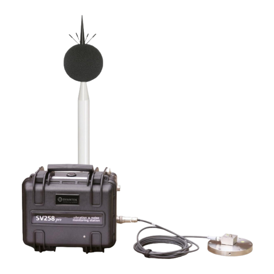
✓ Monitoring station and SB 272 have their own chargers, which are incompatible: SB 270 is a waterproof power supply for SV 258 PRO, whereas SB 273 is an indoor charger for SB 272. ✓ If you use the SV 208A sound measurements set, before installing the station at the measurement site, make sure that the protective caps on the four anti-bird spikes of the SA 277 outdoor microphone protection kit are removed. -
Page 4: Table Of Contents
Features ..........................6 Accessories included ....................... 7 Accessories available ...................... 7 Software options available ....................7 MONITORING STATION SET ............8 SV 258 PRO standard set and optional elements ............8 2.1.1 Waterproof case ......................9 2.1.2 Controller ........................ 11 2.1.3 Sound and Vibration Analyser ................. - Page 5 WEB INTERFACE view ....................35 5.2.1 Live data view ......................36 5.2.2 Configuration views ....................37 5.2.3 STATUS view ......................45 5.2.4 DATA FILES view ....................45 SV 258 PRO MONITORING STATION TECHNICAL DATA ... 46 LIST OF RELATED DOCUMENTS ..........49...
-
Page 6: Introduction
(rev. 4.10.5). 1.1 F EATURES • SV 258 PRO is a portable monitoring station housed in an IP 67 waterproof case dedicated for periodic outdoor measurements. • Human Vibration in buildings measurements in accordance with ISO 2631-1, BS 6472 and DIN 4150-2. -
Page 7: Accessories Included
Note: The software options for the instrument can be purchased at any time as only the introduction of a special unlock code is required for their activation in a specific instrument. Contact your local Svantek distributor for further information and costs for these options. -
Page 8: Monitoring Station Set
(5) are packed inside the second transportation case together with the mounting adapter (8). Additional accessories for the SV 258 PRO system, not included in the standard set, but in many applications, essential for reliable system operation and task performance are:... -
Page 9: Waterproof Case
7. Mast with adjustable height from 1.5 meter to 4 type: meters (SA 206) Manfrotto 269BU. 2.1.1 Waterproof case The SV 258 PRO waterproof case (IP 67) houses and protects the main elements of the monitoring station: • controller, • mobile modem, •... - Page 10 SV 258 PRO User Manual Note: The producer does not recommend removing the controller without a sound reason. Double check that the controller has a good fixation in the socket after reconnecting! The monitoring station case is equipped with the air pressure compensation valve that enables you to open the case easily if the internal pressure is lower than the atmospheric one.
-
Page 11: Controller
The case lid is equipped with an antenna for the mobile modem. 2.1.2 Controller The SV 258 PRO monitoring station is equipped with the SD 270A PRO (or previous modification SD 270 PRO without the TEST button and corresponded LED) controller that integrates and... - Page 12 SV 258 PRO User Manual Very important task of the controller is power distribution - it provides appropriate DC power to every element of the system (managing external power sources such as the SB 270 power supply or an optional solar panel or an external battery).
-
Page 13: Sound And Vibration Analyser
Note: As a part of the SV 258 PRO station SVAN 958A is powered from the external source and doesn’t use its internal batteries. Internal instrument’s batteries must be removed for correct system operation and safety reasons! Note: The station is delivered without internal batteries inside the instrument. - Page 14 SV 258 PRO User Manual There are some important settings, which should be assured in the instrument when it is a part of the monitoring station: 1. Network Setup should be set to GPRS to enable data transmission via the mobile modem (path: <Menu> / Setup / Wireless Com.
-
Page 15: Mobile Modem
SV 84 is a part of the SV 207B set that includes also the metal mounting adapter. Note: See SA 84 Technical Specification on www.svantek.com. Note: Correct connection of the accelerometer is not signalled by the controller, therefore it is... -
Page 16: External Power Supply With Ac/Dc Converter
SV 258 PRO User Manual 2.1.3 External Power Supply with AC/DC converter The SB 270 external power supply is a waterproof Single Output Switching Power Supply which is characterised by: • Universal AC input / Full range (90 ~ 264VAC) •... -
Page 17: Vibration Calibrator
SV 258 PRO User Manual Note: Before installing the station at the measurement site, make sure that the protective caps on the four antibird spikes are removed. It is recommended to use the protective caps during transportation, storage and other operations with the instrument like, laboratory calibration, etc. -
Page 18: External Rechargeable Battery
SV 258 PRO User Manual 2.2.4 External rechargeable battery SB 272 is an external source of DC power for the monitoring station. It includes a Lead-Acid rechargeable battery (33 Ah, 12 V) and is dedicated for outdoor use because of its waterproof case. -
Page 19: Sp 272 - Alarm Lamp
SV 258 PRO User Manual 2.2.6 Alarm Lamp The SP 272 alarm lamp is of type WERMA, LED/Buzzer (12 V DC). The alarm lamp is connecting to the EXTERNAL INTERFACE connector. In this lamp, the buzzer is disabled by default. To enable it: 1. -
Page 20: Operating The Station
The status of powering is indicated at the controller’s panel by a combination of DC, CHARGING, BAT 1 or BAT 2 LEDs (see Table below). Note: It is recommended that the batteries of SV 258 PRO and SB 272 are charged before going on site. -
Page 21: Modes Of Station Operation
SV 258 PRO User Manual Power from Internal battery Power supply External battery Solar panel green • red when • red when CHARGING charging; charging; • green when • green when charged charged • green if charged • when charging, •... -
Page 22: Battery Charging Mode
Activation of the bootstrap mode is indicated by green BAT 1 LED on the controller panel. Note: USB connection between the controller and the PC can be established only if the USB driver for SVANTEK instruments had been previously installed on this PC. The USB driver can be downloaded from www.svantek.com... -
Page 23: Assembling The Station
SV 258 PRO User Manual 2. Insert a mini SIM-card into the slot of the modem. The SIM-card PIN protection must be disabled. 3. A click sound indicates that the SIM-card is in the right position. If necessary, use a tool (e.g. pen) to push the SIM-card fully in. - Page 24 6. If you wish to power the station, connect the power supply cable to the DC SUPPLY socket in the same way. 7. To use Alarm lamp, connect the SP 272 connector to the EXTERNAL INTERFACE socket on the SV 258 PRO case.
-
Page 25: Turning On The Station
SV 258 PRO User Manual 8. Press <Alt>+<Start> on SVAN 958A to turn on the system. 9. The station now is ready for use. 3.6 T URNING ON THE STATION When the remote communication is installed, and the station is fully assembled turn on the SVAN 958A instrument. -
Page 26: Remote Control Via Mobile Connection
SV 258 PRO User Manual REMOTE CONTROL VIA MOBILE CONNECTION The SV 258 PRO station is designed to be operated remotely via a mobile connection. Planning and deploying the remote-control system of the SV 258 PRO station doesn’t require any extensive knowledge in the field of telecommunication. -
Page 27: Interface Functionalities Of Mobile Modem
Once logged in you can use the web interface to work remotely with the monitoring station. Note: Ask your local SVANTEK distributer to create the SvanNET account for you and assign your new station to your SvanNET account. 4.2 I NTERFACE FUNCTIONALITIES OF MOBILE MODEM The mobile modem enables the user a wide spectrum of interfacing capabilities using Internet. -
Page 28: Main Communication Channel
Note: TCP Client mode is used in the SvanNET web-service. SV 258 PRO uses the TCP Client mode for connection with SvanNET (this is the default setting of SVAN 958A). The user PC connects to SvanNET via a web browser or SvanPC++, and the service creates a "bridge"... -
Page 29: Sms / E-Mail Alarming
SMS / E-mail alarming functionality allows SV 258 PRO to inform the user about exceeded thresholds by SMS and/or E-mail notification. SV 258 PRO can send an SMS to a defined number and/or an E-mail to a defined address with alarm, including the current value of the monitored result against the threshold level (see SVAN 958A User Manual). -
Page 30: Svannet User Interface
SV 258 PRO User Manual SVANNET USER INTERFACE The SvanNET interface depends on the package of tools assigned to your account and access level and includes: – projects tools (Project list) – individual stations tools (Station list). If you have the extended SvanNET package, you can use both tools. If you have the standard SvanNET package, only the Station list tool is available. - Page 31 SV 258 PRO User Manual If you click the icon, this icon status information will be displayed: Alert status: blue - everything is OK, red – unregular event is happening. Station connection status: green – online; grey – offline; yellow - the station doesn’t respond to the command for a long time.
-
Page 32: Status View
SV 258 PRO User Manual 5.1.1 STATUS view In the STATUS view you can check the station status and configure status alarms. • To update instrument’s status, click the UPDATE STATUS button. • To configure status alarms Conditions and related Actions for the measurement points, click the STATIONS ALARMS button. - Page 33 SV 258 PRO User Manual • Storage memory Trigger Value: xx MB/GB - alarm is generated when the system detects a decrease in the free storage memory below the selected threshold. • System check (if applicable) Alarm is generated when the system detects failure in execution of the system check procedure (not live check).
-
Page 34: Log Views
SV 258 PRO User Manual 3. click the E-mail button to enter/edit e-mail recipients. 4. click the Assign button to refer alarm to the station(s). 5. Made selections are displayed in the ACTIONS and MEASUREMENT POINTS areas. 5.1.2 LOG views There are three station logs, that register system events, connections and data transfer: •... -
Page 35: Web Interface View
SV 258 PRO User Manual • Data Connection log which registers history of station connections. In the upper line you can: select the required period of records to be displayed and rewind records. • Data transfer log which registers history of data transfers (uploads). -
Page 36: Live Data View
SV 258 PRO User Manual 5.2.1 Live data view The Live data view includes two tabs: OVERVIEW and SPECTRUM RESULTS. The OVERVIEW tab displays current broadband results measured in four channels: 1. Instantaneous Results, measured/averaged by 1-second period and 2. Summary Results, measured/averaged by the Integration period. -
Page 37: Configuration Views
SV 258 PRO User Manual 1. Point your mouse cursor on the plot to readout the values of instantaneous and averaged results for each 1/1 or 1/3 octave band. 2. Point your mouse cursor on the last three bars of the plot to readout the values of instantaneous and averaged three Total results. - Page 38 SV 258 PRO User Manual In the STORAGE tab, you can: 1. Configure the Summary results parameters: switch on/off saving of the Summary results in a file, measurement time and step of saving (Integration period), number of measurement repetitions (Repetition cycles) and switch on/off saving of statistical results (Save statistics) 2.
- Page 39 SV 258 PRO User Manual Note: To ensure saving of Summary results in a file you should switch on the Auto Save function in SVAN 958A (path: <Menu> / Files / Save Options / Auto Save: Number). In this case all files are...
- Page 40 SV 258 PRO User Manual Creating Events To create new event, click the field. The new Event area will appear in which you can: 1. rename the event or delete it, clicking on the appropriate field in the area, 2. configure conditions, clicking on the appropriate button.
- Page 41 SV 258 PRO User Manual In the SPECTRUM CONDITION pop-up window, you can define one 1/3 octave band, Total HP or Total Vel that will be compared with the threshold level. If the measured value (Source) for selected 1/3 band or Total fulfils...
- Page 42 SV 258 PRO User Manual In the TRIGGER CONDITIONS pop-up box, click OK to confirm the defined trigger condition or click CANCEL to reject it. After confirmation (OK) the pop-up box closes, and the selection will be presented in the line of the Trigger button.
- Page 43 SV 258 PRO User Manual In the ADDRESS BOOK pop-up box select the contact and click OK. You can manage the address book adding, deleting and editing contacts. If alarm appears the special message will be sent to the phone number or to the e-mail address informing the recipient about the alarm.
- Page 44 SV 258 PRO User Manual In the EXTERNAL I/O tab, you can: 1. select Mode of the External I/O port: Analog, Digital in, Digital out 2. configure it according to the connected device (for example, the light and sound alarm).
-
Page 45: Status View
SV 258 PRO User Manual 5.2.3 STATUS view The STATUS view is similar to that described in the Chapter 5.1.1. The difference is that instead of STATUS ALARMS, in this view, you can start/stop measurements. 5.2.4 DATA FILES view The file storage window presents a list of files saved in the instrument’s SD-card memory. The list includes only files from a single directory on the memory card and it initially shows the content of the current working directory. -
Page 46: 258 Pro Monitoring Station Technical Data
SV 258 PRO User Manual SV 258 PRO MONITORING STATION TECHNICAL DATA Parameter Value/ Description Physical data SM 258 PRO – 300 x 260 x 190 mm Dimensions SA 250 – 450 x 400 x 155 mm SM 258 PRO – ~10 kg Weight SA 250 –... - Page 47 SV 258 PRO User Manual External DC input voltage: 10,5 V to 28 V Note: When external DC input voltage is in the range 11 V to 15 V, the station is powered from the external DC source but the internal battery is...
- Page 48 SV 258 PRO User Manual 3G modem ® modem type and GeMalto EHS6-T Terminal features Five Bands UMTS (WCDMA/FDD): 800, 850, 900, 1900 and 2100 MHz modem specifications HSDPA Cat.8 / HSUPA Cat.6 data rates DL: max. 7.2 Mbps, UL: max. 5.76 Mbps EDGE Class 12 data rates DL: max.
-
Page 49: List Of Related Documents
SV 258 PRO User Manual LIST OF RELATED DOCUMENTS 1. SVAN 958A User Manual (www.svantek.com) 2. SvanNET User Manual (www.svantek.com) 3. SvanPC++ User Manual (www.svantek.com) 4. SV 84 Specification (www.svantek.com) 5. GeMalto® EHS6 Terminal User Manual (www.gemalto.com) 6. Cinterion® PLS62T-W Gateway (www.thalesgroup.com/IoT)
Need help?
Do you have a question about the SV 258 PRO and is the answer not in the manual?
Questions and answers