Table of Contents
Advertisement
Quick Links
DRW171461AC
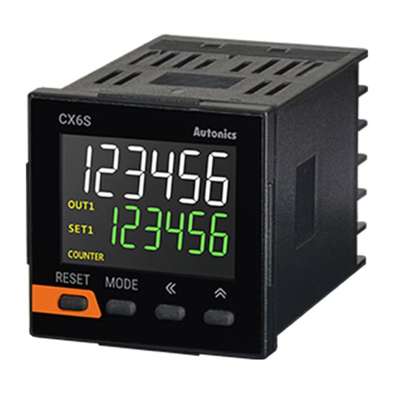
LCD Counter / Timer
CX Series
PRODUCT MANUAL
For your safety, read and follow the considerations written in the instruction
manual, other manuals and Autonics website.
The specifications, dimensions, etc. are subject to change without notice for product
improvement. Some models may be discontinued without notice.
Features
• LCD display with easy-to-read white PV characters
• Input type: voltage input (PNP) / no-voltage input (NPN) selectable (through
parameter setting), universal voltage input type available
• One-shot output time: 0.01 to 99.99 seconds (in 0.01 second increments)
• Compact rear-length size (64.5 mm)
[Counter]
• Prescale value setting range: 0.00001 to 99999.9
• Various input / output modes (11 input modes, 11 output modes)
• Set start point function
• Total count display mode: displays current count and aggregate count simultaneously
[Timer]
• Various output modes (15 output modes)
• Time setting range: 0.001 second to 99999.9 hours
• Set output time to 0 feature
ᜢ ᜫ
Safety Considerations
• Observe all 'Safety Considerations' for safe and proper operation to avoid hazards.
• symbol indicates caution due to special circumstances in which hazards may occur.
Warning
Failure to follow instructions may result in serious injury or death.
01. Fail-safe device must be installed when using the unit with machinery that
may cause serious injury or substantial economic loss. (e.g. nuclear power
control, medical equipment, ships, vehicles, railways, aircraft, combustion
apparatus, safety equipment, crime / disaster prevention devices, etc.)
Failure to follow this instruction may result in personal injury, economic loss or fire.
02. Do not use the unit in the place where flammable / explosive / corrosive gas,
humidity, direct sunlight, radiant heat, vibration, impact, or salinity may be
present.
Failure to follow this instruction may result in explosion or fire.
03. Install on a device panel to use.
Failure to follow this instruction may result in fire or electric shock.
04. Do not connect, repair, or inspect the unit while connected to a power
source.
Failure to follow this instruction may result in fire or electric shock.
05. Check 'Connections' before wiring.
Failure to follow this instruction may result in fire.
06. Do not disassemble or modify the unit.
Failure to follow this instruction may result in fire or electric shock.
Caution
Failure to follow instructions may result in injury or product damage.
01. When connecting the power input and relay output, use AWG 20 (0.50 mm
cable or over, and tighten the terminal screw with a tightening torque of 0.74
to 0.90 N m.
Failure to follow this instruction may result in fire or malfunction due to contact
failure.
02. Use the unit within the rated specifications.
Failure to follow this instruction may result in fire or product damage.
03. Use a dry cloth to clean the unit, and do not use water or organic solvent.
Failure to follow this instruction may result in fire or electric shock.
04. Keep the product away from metal chip, dust, and wire residue which flow
into the unit.
Failure to follow this instruction may result in fire or product damage.
Cautions during Use
• Follow instructions in 'Cautions during Use' .
Otherwise, it may cause unexpected accidents.
• Power supply should be insulated and limited voltage / current or Class 2, SELV power
supply device.
• Use the product, 0.1 sec after supplying power.
• When supplying or turning off the power, use a switch or etc. to avoid chattering.
• Install a power switch or circuit breaker in the easily accessible place for supplying or
disconnecting the power.
• Keep away from high voltage lines or power lines to prevent inductive noise.
In case installing power line and input signal line closely, use line filter or varistor at
power line and shielded wire at input signal line.
Do not use near the equipment which generates strong magnetic force or high
frequency noise.
• This unit may be used in the following environments.
- Indoors (in the environment condition rated in 'Specifications')
- Altitude max. 2,000 m
- Pollution degree 2
- Installation category II
)
2
Advertisement
Table of Contents

Related Manuals for Autonics CX Series


Summary of Contents for Autonics CX Series
- Page 1 For your safety, read and follow the considerations written in the instruction frequency noise. manual, other manuals and Autonics website. • This unit may be used in the following environments. The specifications, dimensions, etc. are subject to change without notice for product - Indoors (in the environment condition rated in ‘Specifications’)
-
Page 2: Ordering Information
RESET input indicator signal input. Dimensions In timer operation - it turns ON for INB / INH or INH indicator INHIBIT signal input OUT1, • Unit: mm, For the detailed drawings, follow the Autonics website. Output indicator Turns ON for the dedicated control output ON OUT2 ■ CX6S Preset value checking, □48 64.5... -
Page 3: Specifications
-|Transparent Guide|- Specifications ■ CX6S (CX6□-□P□F) • 1-stage preset setting model Model CX6S-1P□□ CX6S-2P□□ CX6M-1P□□ CX6M-2P□□ (CX6S-1P□F) CONTACT OUT Display digits 6-digit : 250 VACᜠ 3 A, 30 VDCᜡ 3 A 7-segment (1st, 2nd digits of counting value display: white, setting value display: RESISTIVE LOAD Display method green), 11-segment (the other digits of counting value display: white) LCD... -
Page 4: Mode Setting
-|Transparent Guide|- Parameter Setting Mode Setting • Some parameters are activated / deactivated depending on the model or setting of other [2-stage setting model] parameters. Refer to the description of each parameter. → → [MODE] Auto Display value switching • Counter counting / timer progress and output control are performed even when entering the function setting mode from run mode. -
Page 5: Input Connections
05) In case of CX6□-□P□F model, T1-10 Input logic = NPN, T1-11 Input signal time = 25 ms are fixed, so these parameters are not displayed. Sold Separately: Terminal Cover Error Display and Output Operation • Unit: mm, For the detailed drawings, follow the Autonics website. • When error occurs, the output turns OFF. Display Description Troubleshooting •... -
Page 6: Description Of Function
-|Transparent Guide|- Description of Function Operation Mode Counting chart description ■ Zero blanking (timer) When INA input signal PV is displayed with zero blanking for the highest unit. is falling, it counts. • E.g.) When time range is 99m59.99s and PV is 00m04.05s. DN - 2 Display value: 0:04.05 No counting... - Page 7 -|Transparent Guide|- Output operation description in input operation mode ■ Output operation mode Mode UD - A / B / C Out output of 1-stage preset model operates as same with the OUT2 output of 2-stage preset model. RESET 999999 OUT1 output of 2-stage preset model is operated One-shot output or retained (Hold) output.
-
Page 8: Timer Operation
-|Transparent Guide|- Timer Operation Mode Time chart and output operation description POWER ■ Output operation mode INA (START) INH (INHIBIT) Power reset: There is no memory retention. RESET Initialize the display value and output state when power on again. T.off setting time Power hold: There is memory retention. - Page 9 -|Transparent Guide|- Mode Time chart and output operation description Mode Time chart and output operation description POWER POWER INA (START) INA (START) INH (INHIBIT) INH (INHIBIT) RESET RESET Setting time On_delay Off_delay Display Setting time Display Down On_delay NFD.1 (Interval) Down Off_delay OUT2 (OUT)
-
Page 10: Segment Table
• Output operation mode: OND, OND.1, OND.2, OND.3 UP mode: OUT1 output does not turn ON. DOWN mode: OUT1 output does not turn ON. In 1-stage preset value = 2-stage preset value, when Start signal is applied, OUT1 turns ON immediately. 18, Bansong-ro 513Beon-gil, Haeundae-gu, Busan, Republic of Korea, 48002 www.autonics.com | +82-51-519-3232 | sales@autonics.com...
Need help?
Do you have a question about the CX Series and is the answer not in the manual?
Questions and answers