Table of Contents

Related Manuals for Autonics CX Series


Summary of Contents for Autonics CX Series
- Page 1 User Manual Counters/Timers CX Series Thank you for purchasing an Autonics product. This user manual contains information about the product and its proper use, and should be kept in a place where it will be easy to access. www.autonics.com...
- Page 2 © Copyright Reserved Autonics Co., Ltd.
- Page 3 Preface Preface Thank you for purchasing Autonics product. Please familiarize yourself with the information contained in the Safety Considerations section before using this product. This user manual contains information about the product and its proper use, and should be kept in a place where it will be easy to access.
-
Page 4: User Manual Guide
(www.autonics.com) to download a copy. The manual's content may vary depending on changes to the product's software and other unforeseen developments within Autonics, and is subject to change without prior notice. Upgrade notice is provided through out homepage. ... -
Page 5: User Manual Symbols
Failure to follow instructions can result in serious injury or death. Failure to follow instructions can lead to a minor injury or product damage. An example of the concerned feature's use. Annotation mark. ※1 © Copyright Reserved Autonics Co., Ltd. -
Page 6: Safety Considerations
The specifications and dimensions of user manual are subject to change and some models may be discontinued without notice. Be sure to follow cautions written in the instruction manual, user manual and the technical descriptions (catalog, homepage). © Copyright Reserved Autonics Co., Ltd. -
Page 7: Cautions During Use
Do not use near the equipment which generates strong magnetic force or high frequency noise. This unit may be used in the following environments. ①Indoors (in the environment condition rated in ‘Specifications’) ②Altitude max. 2,000m ③Pollution degree 2 ④Installation category II © Copyright Reserved Autonics Co., Ltd. - Page 8 Cautions during Use viii © Copyright Reserved Autonics Co., Ltd.
-
Page 9: Table Of Contents
Basic Operations ....................35 Operations and functions ................35 5.1.1 Function setting mode ................36 5.1.2 Changing SV mode ................... 37 5.1.3 Checking SV of TOTAL counter ............... 38 5.1.4 Function setting check mode 5.1.5 © Copyright Reserved Autonics Co., Ltd. -
Page 10: Table Of Contents
6.2.4 OUT2 (OUT) output time................64 6.2.5 OUT1 output time ..................65 6.2.6 Input logic ....................65 6.2.7 Input signal time ..................65 6.2.8 Memory protection ..................66 6.2.9 6.2.10 Key lock ....................66 © Copyright Reserved Autonics Co., Ltd. - Page 11 Timer ‘0’ time setting ..................77 Timer output mode for ‘0’ time setting ............77 6.4.1 Operations by output mode (‘0’ time setting) ..........77 6.4.2 Factory Default ..................85 Common ......................85 Counter ......................85 Timer ........................86 © Copyright Reserved Autonics Co., Ltd.
- Page 12 Table of Contents © Copyright Reserved Autonics Co., Ltd.
-
Page 13: Features
If a compo onent is miss sing or dama aged, please e contact Auto onics or your r distributor. © Copyrig ht Reserved d Autonics C o., Ltd. -
Page 14: Product Overview
1 Product Overview Sold separately 1.2.2 (1) Terminal cover RSA-COVER (48×48mm) RMA-COVER (72×72mm) © Copyright Reserved Autonics Co., Ltd. -
Page 15: Ordering Information
DIN W72 × H72mm 1-stage setting ④ Output 2-stage setting 24VAC 50/60Hz, 24-48VDC ⑤ Power supply 100-240VAC 50/60Hz Voltage input (PNP)/no-voltage input (NPN) No mark selectable type ⑥ Signal input method Free voltage input © Copyright Reserved Autonics Co., Ltd. -
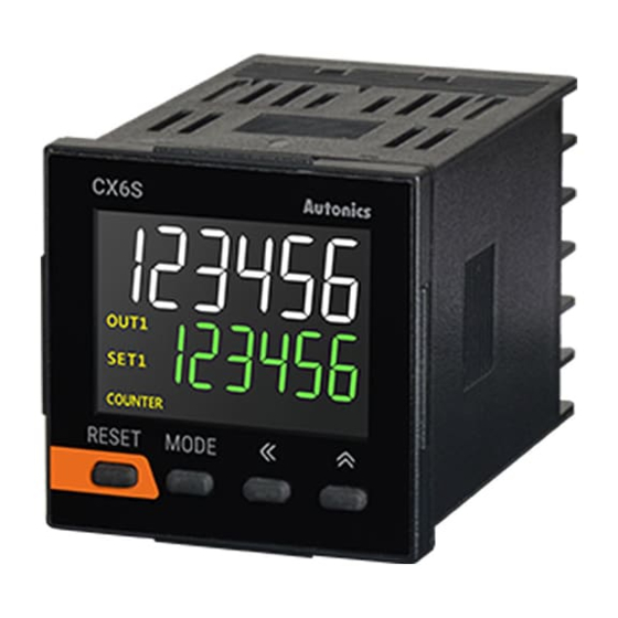
Page 16: Unit Description
RUN mode: Displays counting value for counter operation or time progress value for timer operation. Function setting mode: Displays parameter. (2) Setting value display component (green) RUN mode: Displays setting value. Function setting mode: Displays setting content. © Copyright Reserved Autonics Co., Ltd. - Page 17 RUN mode: Press the Press the key to change SV and move SV (SET, SET1, SET2) digits. Changing SV mode: Press the key to change digits. Changing SV mode: Increases SV. Function setting mode: Changes the settings. © Copyright Reserved Autonics Co., Ltd.
- Page 18 1 Product Overview ※1: This is for the voltage input (PNP)/no-voltage input (NPN) selectable model (CX6□-□□). © Copyright Reserved Autonics Co., Ltd.
-
Page 19: Specifications
SET error In case of signal ON start: max. ±0.01% ±0.03s Voltage error [CX6□-□□F] - In case of power ON start: max. ±0.01% ±0.08s Temperature error In case of signal ON start: max. ±0.01% ±0.06s © Copyright Reserved Autonics Co., Ltd. - Page 20 Approx. 161g Approx. 234g Approx. 239g CX6□-□□ (approx. 111g) (approx. 116g) (approx. 169g) (approx. 174g) AC/DC voltage Approx. 154g Approx. 159g Approx. 232g Approx. 237g CX6□-□□F (approx. 109g) (approx. 114g) (approx. 167g) (approx. 172g) © Copyright Reserved Autonics Co., Ltd.
- Page 21 ※1: This is for the voltage input (PNP)/no-voltage input (NPN) selectable model (CX6□-□□). ※2: The weight includes packaging. The weight in parenthesis for unit only. ※Environment resistance is rated at no freezing or condensation. © Copyright Reserved Autonics Co., Ltd.
- Page 22 2 Specifications © Copyright Reserved Autonics Co., Ltd.
-
Page 23: Dimensions
3 Dimensions Dimensions (unit: mm) CXS Series CXM Series © Copyright Reserved Autonics Co., Ltd. -
Page 24: Panel Cut-Out Dimension
3 Dimensions Panel cut-out dimension (unit: mm) CXS Series 3.3.1 CXM Series 3.3.2 © Copyright Reserved Autonics Co., Ltd. -
Page 25: Bracket
3 Dimensions Bracket (unit: mm) CXS Series 3.4.1 CXM Series 3.4.2 © Copyright Reserved Autonics Co., Ltd. - Page 26 3 Dimensions © Copyright Reserved Autonics Co., Ltd.
-
Page 27: Connection Method
4 Connection Method Connection Method Connection CXS Series 4.1.1 (1) Voltage input(PNP)/no-voltage input(NPN) selectable model CX6S-1P□ ※1: AC voltage type: 100-240VAC 50/60Hz AC/DC voltage type: 24VAC 50/60Hz, 24-48VDC © Copyright Reserved Autonics Co., Ltd. - Page 28 4 Connection Method CX6S-2P2 CX6S-2P4 ※2: AC/DC voltage type: 24VAC 50/60Hz, 24-48VDC ※3: AC voltage type: 100-240VAC 50/60Hz © Copyright Reserved Autonics Co., Ltd.
- Page 29 4 Connection Method (2) Free voltage input model CX6S-1P□F CX6S-2P2F CX6M-2P4F ※1: AC voltage type: 100-240VAC 50/60Hz AC/DC voltage type: 24VAC 50/60Hz, 24-48VDC © Copyright Reserved Autonics Co., Ltd.
- Page 30 4 Connection Method CXM Series 4.1.2 (1) Voltage input(PNP)/no-voltage input(NPN) selectable model CX6M-1P□ CX6M-2P□ ※1: AC voltage type: 100-240VAC 50/60Hz AC/DC voltage type: 24VAC 50/60Hz, 24-48VDC © Copyright Reserved Autonics Co., Ltd.
- Page 31 4 Connection Method (2) Free voltage input model CX6M-1P□F CX6M-2P□F ※1: AC voltage type: 100-240VAC 50/60Hz AC/DC voltage type: 24VAC 50/60Hz, 24-48VDC © Copyright Reserved Autonics Co., Ltd.
-
Page 32: Input And Output Connection
Solid-state input (standard sensor: PNP output type sensor) Contact input (2) No-voltage input (NPN) Solid-state input (standard sensor: NPN output type sensor) Contact input ※1: CP1, CP2(INHIBIT), SET input part ※2: Set counting speed as 1 or 30cps. © Copyright Reserved Autonics Co., Ltd. -
Page 33: Output Connection
For solid state output, select load power and load not to be over (max. 30VDC, 100mA), switching capacity. Do not supply reverse polarity voltage. ※1: For using inductive load (relay, etc), connect surge absorber (diode, varistor, etc) at the both ends of load. © Copyright Reserved Autonics Co., Ltd. - Page 34 4 Connection Method © Copyright Reserved Autonics Co., Ltd.
-
Page 35: Counter Mode
5 Counter mode Counter mode Basic Operations Operations and functions 5.1.1 © Copyright Reserved Autonics Co., Ltd. -
Page 36: Function Setting Mode
: When changing the setting of shaded parameters, all output turn OFF. ※ When returning RUN mode, PV is reset. ※In case of 1-stage setting model(CX6□-1P□□), OUT1output time does not appear. OUT2 output time is displayed as OUtT. © Copyright Reserved Autonics Co., Ltd. -
Page 37: Changing Sv Mode
In case of 1-stage setting model (CX6□-1P□□), SET2 is displayed as SET and SET1 is not displayed. After setting SV at each parameter, press the key to save SV and it moves next parameter setting or returns to RUN mode. © Copyright Reserved Autonics Co., Ltd. -
Page 38: Checking Sv Of Total Counter
, press the key to reset TOTAL counter counting ※1 value and the current counting value. ※1: This is for the voltage input(PNP)/no-voltage input(NPN) selectable model (CX6□-□□). TOTAL counter display mode is only when counter operation. © Copyright Reserved Autonics Co., Ltd. -
Page 39: Parameter Setting
※Decimal point is applied to PV and SV. Min. reset , unit: ms time [RESET] ※Set min. width of external reset signal input. ※2 Input logic ※2 NPN: No-voltage input, PNP: Voltage input [SIG] © Copyright Reserved Autonics Co., Ltd. - Page 40 Decimal point : Set the decimal point for display value regardless of prescale value. Prescale decimal point : Set the decimal point for prescale value of counting value regardless of display value. © Copyright Reserved Autonics Co., Ltd.
-
Page 41: Counter/Timer
※In case of 1-stage setting model(CX6□-1P□□), OUT1output time does not appear. OUT2 output time is displayed as OUtT. ※In case of F, N, S, T, D output mode, OUT2 does not appear. (fixed as HOLD) © Copyright Reserved Autonics Co., Ltd. -
Page 42: Out1 Output Time
Press the key to move digit to the 2nd digit. Press the key to set as 1 of 2nd digit. Press the key to save SV and moves to next parameter. (3) Setting parameter order © Copyright Reserved Autonics Co., Ltd. -
Page 43: Decimal Point
Set decimal point of counting value and SV in RUN mode. Min. reset time 5.2.8 Select min. signal width of the external RESET signal input. (unit: ms) Input logic 5.2.9 Select external signal input logic; NPN or PNP input. © Copyright Reserved Autonics Co., Ltd. -
Page 44: Prescale
Set decimal point [DP] as [-----.-] mode, prescale decimal point [SClDP] as [---.---] and prescale value[SCL] parameter as [ )069 ] at function setting mode. It is available to control conveyer position by 0.1mm unit. © Copyright Reserved Autonics Co., Ltd. -
Page 45: Prescale Decimal Point
Set decimal point of prescale referring to [5.2.11 prescale decimal point]. Prescale value setting ② TOTAL Counter 5.2.13 Set TOTAL counter operation ON/OFF. ※In case of TOTAL counter OFF and at RUN mode, press the key and it changes to SV display mode. © Copyright Reserved Autonics Co., Ltd. -
Page 46: Start Point Value
Setting range of start point value is linked with decimal point [DP]. ※1: This is for the voltage input(PNP)/no-voltage input(NPN) selectable model (CX6□-□□). ※Start point for F output mode ※Start point for C output mode © Copyright Reserved Autonics Co., Ltd. -
Page 47: Memory Protection
※CLR: Resets the counting value when power OFF. REC: Maintains the counting value when power OFF. (memory protection) Key lock 5.2.16 Set key lock function depending on counter/timer operation. ※lOFF: Unlock keys. LOc1: Locks key. LOc2: Locks keys. LOc3: Locks keys. © Copyright Reserved Autonics Co., Ltd. -
Page 48: Input Mode
※When INA input signal is falling ( ), it counts. ※INA: Counting input ※INB: No counting input Up-3 [ UP-3 ] ※When INA or INB input signal is rising ( ), it counts. ※INA: Counting input ※INB: Counting input © Copyright Reserved Autonics Co., Ltd. - Page 49 ※When INA input signal is falling ( ) , it counts. ※INA: Counting input ※INB: No counting input Down-3 DN-3 ※When INA or INB input signal is rising ( ) , it counts. ※INA: Counting input ※INB: Counting input © Copyright Reserved Autonics Co., Ltd.
- Page 50 ※1: This is for the voltage input(PNP)/no-voltage input(NPN) selectable model (CX6□-□□). : over min. signal width, : over than 1/2 of min. signal width. If the signal is smaller than ※ these width, it may cause counting error (±1). © Copyright Reserved Autonics Co., Ltd.
- Page 51 Open ※Min. signal width by counting speed (1cps=1Hz) CX6□-□□ Counting speed Min. signal width 1cps 500ms 30cps 16.7ms 300cps 1.67ms 1kcps 0.5ms 5kcps 0.1ms CX6□-□□F Counting speed Min. signal width 20cps 25ms © Copyright Reserved Autonics Co., Ltd.
-
Page 52: Output Mode
※After count-up, counting value display is reset after one-shot output time of OUT2 and it counts simultaneously. ※OUT1 retained output will be off after OUT2 one-shot time. ※OUT1 one-shot output time is operated regardless of OUT2 output. © Copyright Reserved Autonics Co., Ltd. - Page 53 ※OUT1 one-shot output time is operated regardless of OUT2 output. A [A] ※After count-up, counting display value and OUT1 retained output are maintained until RESET input is applied. ※OUT1 one-shot output time is operated regardless of OUT2 output. © Copyright Reserved Autonics Co., Ltd.
- Page 54 ※OUT1 is available to set as ‘0’ regardless of output mode. The output for '0' setting executes. ※In case of C, R, P, Q output mode for OUT2, setting ‘0’ is not available. © Copyright Reserved Autonics Co., Ltd.
-
Page 55: Output Operation For Other Conditions
In case of UP, UP-1, UP-2, UP-3, UD-A , UD-B , UD-C mode, output of OUT1 turns ON ※1 ※1 when RESET ON to OFF. ※1: This is for the voltage input(PNP)/no-voltage input(NPN) selectable model (CX6□-□□). © Copyright Reserved Autonics Co., Ltd. -
Page 56: When Set1 Is Larger Or Equal Than Set2 At Down Mode
When SET1 is larger or equal than SET2 at down mode 5.5.2 (1) When SET1 > SET2 Output of OUT1 does not execute. ※Output mode: F (2) When SET1 = SET2 Output of OUT1 turns ON for RESET OFF. ※Output mode: F © Copyright Reserved Autonics Co., Ltd. -
Page 57: Timer Mode
6 Timer mode Timer mode Basic Operations Operations and functions 6.1.1 © Copyright Reserved Autonics Co., Ltd. -
Page 58: Function Setting Mode
※Even though entering RUN mode and function setting mode, it operates timer and output control. ※When changing operation setting value at function setting mode, all output turn OFF and it is reset when it returns to RUN mode. © Copyright Reserved Autonics Co., Ltd. -
Page 59: Changing Sv Mode
In case of 2-stage setting model (CX6□-2P□□) and OND, ONd1, ONd2, ONd3 output mode, it is available. In run mode, whenever pressing the key, the setting value display component displays SET1, SET2 SV in turn. In case of 1-stage setting model (CX6□-1P□□), it is not available. © Copyright Reserved Autonics Co., Ltd. -
Page 60: Reset
When time range is 99m59.99s and PV is 00m04.05s, zero blanking is applied to minute which is the highest unit. At the below digits of decimal point, it is not applied. It displays as “0:04.05”. © Copyright Reserved Autonics Co., Ltd. -
Page 61: Parameter Setting
REC: Maintains the counting value when power OFF. (memory protection) Key lock ※lOFF: Unlock keys, key lock indicator OFF [LOCK] LOc1: Locks key, key lock indicator ON LOc2: Locks keys, key lock indicator ON LOc3: Locks keys, key lock indicator ON © Copyright Reserved Autonics Co., Ltd. - Page 62 ※5: In case of 1-stage setting model(CX6□-1P□□), OUT1output time does not appear. OUT2 output time is displayed as OUtT. ※6: In case of free voltage input model (CX6□-□□F), this parameter does not appear due to fixed setting. © Copyright Reserved Autonics Co., Ltd.
-
Page 63: Counter/Timer
OND, ONd1, ONd2, ONd3, FLK, FLk1, FLk2, INT, INt1, OFD, NFD, NFd1, INTG, ※ 1 , ONtD TOTAL 2-stage setting model (CX6□-2P□□) ※ 2 , OFD, NFD, NFd1, OND, ONd1, ONd2, ONd3, FLK, FLk1, FLk2, INT, INt1, INt2 ※ 1 , ONtD INTG, TOTAL © Copyright Reserved Autonics Co., Ltd. -
Page 64: Time Range
Press the keys to set as 5 of the 2nd digit. Press the key to save SV and moves to next parameter. © Copyright Reserved Autonics Co., Ltd. -
Page 65: Out1 Output Time
※In case of 1-stage setting model (CX6□-1P□□), OUT1 dose not appear. Input logic 6.2.7 Select external signal input logic; NPN or PNP input. Input signal time 6.2.8 Select min. signal width of the external signal input. (unit: ms) © Copyright Reserved Autonics Co., Ltd. -
Page 66: Memory Protection
※1: This is for the voltage input(PNP)/no-voltage input(NPN) selectable model (CX6□-□□). Key lock 6.2.10 Set key lock function depending on counter/timer operation. ※lOFF: Unlock keys. LOc1: Locks key. LOc2: Locks keys. LOc3: Locks keys. © Copyright Reserved Autonics Co., Ltd. -
Page 67: Output Operation Mode
※Power RESET: There is no memory protection. (resets the display value when power is off) ※Power Hold: There is memory protection. (memorizes the display value at the moment of power off, indicates the memorized display value when power is resupplied.) © Copyright Reserved Autonics Co., Ltd. - Page 68 ※Power RESET: There is no memory protection. (resets the display value when power is off) ※Power Hold: There is memory protection. (memorizes the display value at the moment of power off, indicates the memorized display value when power is resupplied.) © Copyright Reserved Autonics Co., Ltd.
- Page 69 ※Power RESET: There is no memory protection. (resets the display value when power is off) ※Power Hold: There is memory protection. (memorizes the display value at the moment of power off, indicates the memorized display value when power is resupplied.) © Copyright Reserved Autonics Co., Ltd.
- Page 70 ※Power RESET: There is no memory protection. (resets the display value when power is off) ※Power Hold: There is memory protection. (memorizes the display value at the moment of power off, indicates the memorized display value when power is resupplied.) © Copyright Reserved Autonics Co., Ltd.
- Page 71 ※Power RESET: There is no memory protection. (resets the display value when power is off) ※Power Hold: There is memory protection. (memorizes the display value at the moment of power off, indicates the memorized display value when power is resupplied.) © Copyright Reserved Autonics Co., Ltd.
- Page 72 ※Power RESET: There is no memory protection. (resets the display value when power is off) ※Power Hold: There is memory protection. (memorizes the display value at the moment of power off, indicates the memorized display value when power is resupplied.) © Copyright Reserved Autonics Co., Ltd.
- Page 73 ※Power RESET: There is no memory protection. (resets the display value when power is off) ※Power Hold: There is memory protection. (memorizes the display value at the moment of power off, indicates the memorized display value when power is resupplied.) © Copyright Reserved Autonics Co., Ltd.
- Page 74 ※Power RESET: There is no memory protection. (resets the display value when power is off) ※Power Hold: There is memory protection. (memorizes the display value at the moment of power off, indicates the memorized display value when power is resupplied.) © Copyright Reserved Autonics Co., Ltd.
- Page 75 ※Power RESET: There is no memory protection. (resets the display value when power is off) ※Power Hold: There is memory protection. (memorizes the display value at the moment of power off, indicates the memorized display value when power is resupplied.) © Copyright Reserved Autonics Co., Ltd.
- Page 76 OFF. (the display value is reset when power turns OFF) ※When memory protection setting is ON, it memorizes the display value when power turns OFF. When re-suppling the power, it displays the memorized value. © Copyright Reserved Autonics Co., Ltd.
-
Page 77: Timer '0' Time Setting
OND, ONd1, ONd2, ONd3, NFD, NFd1 Operations by output mode (‘0’ time setting) 6.4.2 (1) OND (Signal ON Delay) mode [OND] Set ‘0’ for setting time 1. UP mode DOWN mode Set ‘0’ for setting time 2. © Copyright Reserved Autonics Co., Ltd. - Page 78 6 Timer mode (2) OND.1 (Signal ON Delay1) mode [OND.1] Set ‘0’ for setting time 1. UP mode DOWN mode Set ‘0’ for setting time 2. © Copyright Reserved Autonics Co., Ltd.
- Page 79 6 Timer mode (3) OND.2 (Power ON Delay2) mode [OND.2] Set ‘0’ for setting time 1. UP mode DOWN mode Set ‘0’ for setting time 2. © Copyright Reserved Autonics Co., Ltd.
- Page 80 6 Timer mode (4) OND.3 (Signal ON Delay3) mode [ONd.3] Set ‘0’ for setting time 1 UP mode DOWN mode Set '0' for setting time 2 © Copyright Reserved Autonics Co., Ltd.
- Page 81 6 Timer mode (5) NFD (ON-OFF Delay) mode [NFD] Set ‘0’ for Off_Delay setting time. Set ‘0’ for On_Delay setting time. © Copyright Reserved Autonics Co., Ltd.
- Page 82 6 Timer mode (6) NFD.1 (ON-OFF Delay1) mode [NFD.1] Set ‘0’ for Off_Delay setting time. Set ‘0’ for On_Delay setting time. © Copyright Reserved Autonics Co., Ltd.
- Page 83 OUT1 oututput does not turn ON. When timer setting value 1 (SET1) and setting value 2 (SET2) are same, OUT1 output turns ON when applied the start signal. Output mode: OND (Signal On Delay) Output mode: ONd1 (Signal ON Delay 1) © Copyright Reserved Autonics Co., Ltd.
- Page 84 6 Timer mode Output mode: ONd2 (Signal On Delay 2) Output mode: ONd3 (Signal On Delay 3) © Copyright Reserved Autonics Co., Ltd.
-
Page 85: Factory Default
000000 DATA ※1: In case of 1-stage setting model (CX6□-1P□□), OUT1 output time does not appear. OUT2 output time is displayed as OUtT. ※2: This is for the voltage input(PNP)/no-voltage input(NPN) selectable model (CX6□-□□). © Copyright Reserved Autonics Co., Ltd. -
Page 86: Timer
IN-T 20ms ※1: For 1-stage setting model (CX6□-1P□□), OUT1 does not appear. The output time of OUT2 is displayed as OUtT. ※2: This is for the voltage input (PNP)/no-voltage input (NPN) selectable model (CX6□-□□). © Copyright Reserved Autonics Co., Ltd. - Page 87 * Dimensions or specifications on this manual are subject to change and some models may be discontinued without notice. MCC-CXU1-V1.5-1902US...
Need help?
Do you have a question about the CX Series and is the answer not in the manual?
Questions and answers