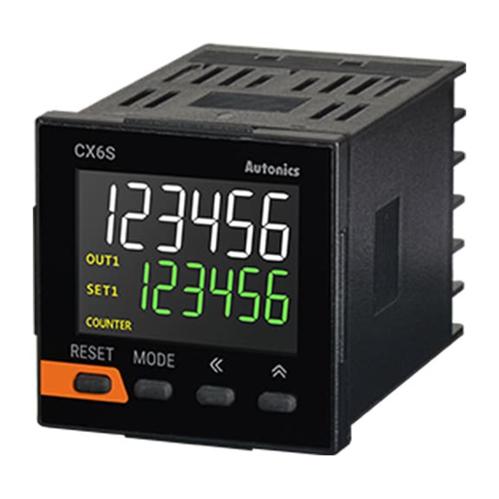
Autonics CX Series Manual

Autonics CX Series Manual

Lcd display counter/timer
Hide thumbs Also See for CX Series:

Advertisement

CX Series
DIN W48×H48mm, W72×H72mm LCD Display Counter/Timer
Features
Improved visibility with LCD display
Input method: voltage input (PNP)/no-voltage input (NPN) selectable model (by parameter setting),
Free voltage input model
Setting range of one-shot output time: 0.01 sec to 99.99 sec by 0.01 sec unit
Mounting space saving with compact design (back length: 64.5mm)
[Counter]
Setting range of prescale value: 0.00001 to 99999.9
Various input/output mode (input: 11 types, output: 11 types)
Start point (counting value reset) setting
TOTAL counter display mode
: Displays the present value and the integrated value
simultaneously.
[Timer]
Various output mode (15 types)
Wide time setting range: 0.001 sec to 99999.9 hour
'0' time setting function
Please read "Safety Considerations" in operation
manual before using.
Manual
For the detail information, please refer to user manual, and be sure to follow cautions written in the technical descriptions (catalog,
homepage).
Visit our homepage (www.autonics.com) to download manuals.
Ordering Information
CX
6
S
Size
Display digit
Item
J-8
-
1P
4
F
Signal input method
Power supply
Output
Voltage input (PNP)/no-voltage input (NPN)
No mark
selectable type
F
Free voltage input
2
24VAC 50/60Hz, 24-48VDC
4
100-240VAC 50/60Hz
1P
1-stage setting
2P
2-stage setting
S
DIN W48×H48mm
M
DIN W72×H72mm
6
999999 (6-digit)
CX
LCD Display counter/Timer

Advertisement

Table of Contents
loading
Need help?

Need help?

Do you have a question about the CX Series and is the answer not in the manual?

Questions and answers

Subscribe to Our Youtube Channel

Summary of Contents for Autonics CX Series

  • Page 1 Manual For the detail information, please refer to user manual, and be sure to follow cautions written in the technical descriptions (catalog, homepage). Visit our homepage (www.autonics.com) to download manuals. Ordering Information Voltage input (PNP)/no-voltage input (NPN) No mark...
  • Page 2: Specifications

    LCD Display Counter/Timer Specifications Photoelectric Model CX6S-1P CX6S-2P CX6M-1P CX6M-2P Sensors Display digits 6-digit 7-segment (1st, 2nd digits of counting value display: white, setting value display: green) LCD method, Fiber Optic Display method 11-segment (the other digits of counting value display: white) LCD method, Sensors Operation display part: yellow LCD method Counting value 4.1×10.1mm...
  • Page 3 CX Series Connections CX6S Series 1. Voltage input (PNP), no-voltage input (NPN) selectable model CX6S-1P CX6S-2P2 CX6S-2P4 CONTACT OUT: CONTACT OUT1/OUT2: CONTACT OUT1/OUT2: 250VAC 3A, 30VDC 3A 250VAC 3A, 30VDC 3A 250VAC 3A, 30VDC 3A RESISTIVE LOAD RESISTIVE LOAD RESISTIVE LOAD...
  • Page 4 LCD Display Counter/Timer Connections Photoelectric Sensors CX6M Series 1. Voltage input (PNP), no-voltage input (NPN) selectable model Fiber Optic Sensors CX6M-1P CX6M-2P Door/Area CONTACT OUT: 250VAC 3A, 30VDC 3A CONTACT OUT1/OUT2: 250VAC 3A, 30VDC 3A Sensors RESISTIVE LOAD RESISTIVE LOAD Proximity Sensors OUT2...
  • Page 5 CX Series Dimensions (unit: mm) CX6S Series Panel cut-out CX6S Series Min. 65 64.5 +0.6 CX6M Series 64.5 CX6M Series Min. 91 +0.7 Bracket CX6S Series CX6M Series ±0.2 48.6 30.6 +0.2 23.9 Terminal cover (sold separately) CX6S Series CX6M Series (RSA-COVER, 48×48mm)
  • Page 6: Unit Description

    LCD Display Counter/Timer Unit Description Photoelectric CX6S Series CX6M Series Sensors Fiber Optic Sensors Door/Area Sensors Proximity Sensors Pressure Sensors Rotary Encoders Connectors/ Connector Cables/ Sensor Distribution Boxes/Sockets 1. Counting value display component (white) RUN mode: Displays counting value for counter operation or time progress value for timer operation. Temperature Function setting mode: Displays parameter.
  • Page 7: Input Connections

    CX Series Input Connections No-voltage input (NPN) ● Solid-state input (standard sensor: NPN output type sensor) ● Contact input Sensor Counter/Timer Sensor Counter/Timer Counter/Timer Brown Brown +12V +12V +12V 5.4kΩ 5.4kΩ 5.4kΩ ※ 1 ※1 Black Black ※2 Inner circuit...
  • Page 8: Counter Mode

    LCD Display Counter/Timer Operations and Functions (counter/timer) Photoelectric Sensors Function setting mode Fiber Optic Sensors Changing SV mode 3sec (RUN mode) Door/Area Sensors 3sec (CX6 - Function setting Proximity 1sec TOTAL SET1 SET2 Sensors RUN mode 1sec check mode counter value value Pressure...
  • Page 9 CX Series ● Function setting mode ※1: In case of free voltage input model ( CX6 - F) , these parameters do not appear due to fixed setting. ※2: This parameter is for the voltage input(PNP)/no-voltage input(NPN) selectable model (CX6 - ※...
  • Page 10 LCD Display Counter/Timer Parameter Setting (Counter) key: moves parameters, key: changes parameter setting value) Photoelectric Sensors Parameter Parameter setting value Fiber Counter/Timer ※ COUNT: Counter Optic COUNT TIME [C-T] TIME: Timer Sensors UP-1 UP-2 UP-3 DN-1 Input mode Door/Area [I nM ] UD-C ※1 UD-B...
  • Page 11 CX Series Input Operation Mode (Counter) Input mode Counting chart Operation No counting ※ W hen INA is counting input, INB is no counting input. No counting [ UP ] When INB is counting input, INA is no counting input.
  • Page 12 LCD Display Counter/Timer Input Operation Mode (Counter) Photoelectric Sensors Input mode Counting chart Operation Fiber Optic Sensors ※ W hen INA or INB input signal is rising Down-3 ) , it counts. Door/Area [ DN-3 ] ※ I NA: Counting input Sensors ※ I NB: Counting input Count...
  • Page 13 CX Series Output Operation Mode (Counter) One-shot output (0.01 to 99.99 sec) One-shot output Retained output Retained output Input mode Output Operation mode Up, Up-1, 2, 3 Down, Down-1, 2, 3 Up/Down A, B, C RESET 999999 ※ A fter count-up, counting display...
  • Page 14: Output Operation For Other Conditions

    LCD Display Counter/Timer Output Operation Mode (Counter) Retained output Coincidence output Photoelectric Sensors Input mode Output Operation mode Up/Down A, B, C Fiber Optic Sensors RESET ※ O UT1 keeps ON status in following 999999 condition Door/Area SET2 Sensors SET1 : Counting display value ≥...
  • Page 15 CX Series Prescale Function (Counter) This function is to set and display calculated unit for actual length, liquid, position, etc. It is called “prescale value” for measured length, liquid, or position, etc per 1 pulse. For example, when moving L, the desired length to be measured, and P, the number of pulses per 1 revolution of a rotary encoder, occurs, prescale value is L/P.
  • Page 16: Timer Mode

    LCD Display Counter/Timer Timer mode Photoelectric ● Changing SV mode Sensors When input signal is ON during changing SV, it operates counting and output control. It is available to set SV as '0' and the dedicated output for SV '0' occurs. Fiber Optic There are output mode which cannot set SV as '0'.
  • Page 17 CX Series ● Switching display of the setting value display component Select the display value at the setting value display component. Depends on output mode, there are manual display switching and auto display switching. - Manual display switching 1) In case of 2-stage setting model (CX6 -2P ) and OND , ONd1 , ONd2 , ONd3 output mode, it is available.
  • Page 18 LCD Display Counter/Timer Parameter Setting (Timer) key: moves parameters, key: changes parameter setting value) Photoelectric Parameter Parameter setting value Sensors Counter/Timer ※ COUNT: Counter COUNT TIME [C-T] TIME: Timer Fiber Optic Sensors Up/Down mode ※UP: Time progresses from '0' to the setting time. [U-D] DN: Time progresses from the setting time to '0'.
  • Page 19 CX Series One-shot output (0.01 to 99.99 sec) One-shot output Retained output Output Operation Mode (Timer) Retained output Output Time chart mode Operation Signal On Delay (Power RESET) 1)Time starts when INA signal turns ON. POWER 2) When INA signal turns OFF, INA(START) time resets.
  • Page 20 LCD Display Counter/Timer One-shot output (0.01 to 99.99 sec) One-shot output Retained output Output Operation Mode (Timer) Retained output Photoelectric Output Sensors Time chart mode Operation Flicker (Power RESET) Fiber Optic Sensors 1)Time starts when INA signal turns ON. 2) When INA signal is ON : Power ON Time Start is operated.
  • Page 21 CX Series One-shot output (0.01 to 99.99 sec) One-shot output Retained output Output Operation Mode (Timer) Retained output Output Time chart mode Operation Flicker 2 (Power Hold) 1) Time starts when INA signal turns ON and the display value at the moment when power is off is memorized.
  • Page 22 LCD Display Counter/Timer One-shot output (0.01 to 99.99 sec) One-shot output Retained output Output Operation Mode (Timer) Retained output Photoelectric Output Sensors Time chart mode Operation Interval 2 (Power RESET) Fiber Optic 1) Time starts when INA signal is ON, Sensors and resets when INA signal is OFF.
  • Page 23 CX Series One-shot output (0.01 to 99.99 sec) One-shot output Retained output Output Operation Mode (Timer) Retained output Output Time chart mode Operation On-Off Delay1 (Power RESET) 1) When INA input turns ON, time progresses and output turns ON after POWER On_Delay time.
  • Page 24 LCD Display Counter/Timer One-shot output (0.01 to 99.99 sec) One-shot output Retained output Output Operation Mode (Timer) Retained output Photoelectric Output Sensors Time chart Operation mode ※ON time indicate mode of INA signal. When memory protection setting is OFF Fiber Optic 1) Time reset start operates when INA Sensors...
  • Page 25: Timer '0' Time Setting

    CX Series One-shot output (0.01 to 99.99 sec) Timer '0' Time Setting Retained output Available output operation mode to set '0' time setting ONd1 ONd2 ONd3 NFd1 One-shot output Retained output Operation according to output mode (at 0 time setting) 1) OND (Signal ON Delay) mode [OND] ●...
  • Page 26: Factory Default

    LCD Display Counter/Timer 6) NFD.1 (ON-OFF Delay1) mode NFd1 Photoelectric Set ‘0’ for Off_Delay setting time. Set ‘0’ for On_Delay setting time. Sensors INA (START) INA (START) Fiber RESET RESET Optic Sensors Off_Delay On_Delay Door/Area Display Display Sensors Off_Delay On_Delay Down Down OUT2...

Table of Contents

Save PDF