
Related Manuals for Samsung AM AN1PCH Series


Summary of Contents for Samsung AM AN1PCH Series
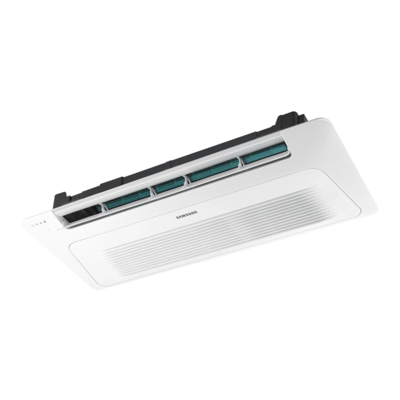
- Page 1 Air conditioner Installation manual AM***AN1PCH • Thank you for purchasing this Samsung air conditioner. • Before operating this unit, please read this manual carefully and retain it for future reference.
-
Page 2: Table Of Contents
Contents Safety Information Installation Procedure Step 1 Checking and preparing accessories Step 2 Choosing the installation location Step 3 Optional: Insulating the body of the indoor unit Step 4 Installing the indoor unit Step 5 Purging inert gas from the indoor unit Step 6 Cutting and flaring the pipes Step 7 Connecting the assembly pipes to the refrigerant pipes Step 8 Performing the gas leak test... -
Page 3: Safety Information
• This manual explains how to install an indoor unit with equipped. a split system with two SAMSUNG units. The use of other types of units with different control systems may damage the units and invalidate the warranty. The manufacturer shall not be responsible for damages arising from the use of non compliant units. - Page 4 Safety Information • This unit is a partial unit air conditioner, complying • If any gas or impurities, except R-410A refrigerant, with partial unit requirements of this International come into the refrigerant pipe, serious problem may Standard, and must only be connected to other occur and it may cause injury.
- Page 5 – When extension wiring is required due to power line damage, refer to Step 13 Optional: Extending the power cable in the installation manual. CAUTION Make sure that you earth the cables. • Do not connect the earth wire to the gas pipe, water pipe, lighting rod or telephone wire.
-
Page 6: Installation Procedure
Installation Procedure Installation Procedure Step 1 Checking and preparing Step 2 Choosing the installation accessories location The following accessories are supplied with the indoor unit. The type and quantity may differ, depending on the Installation location requirements specifications. • There must be no obstacles near the air inlet and outlet. - Page 7 Indoor unit dimensions Slim 1way cassette (Small) Unit: inch(mm) 33.86(860) (Ceiling opening dimension) 31.18(792) Space of suspension bolts) 16.93(430) Ceiling 37.8(960) Outlet 2.64(67) AM005AN1PCH* Model AM007AN1PCH* inch(mm) 5.28(134) inch(mm) 7.09(180) Liquid pipe connection inch(mm) Ø1/4"(6.35) Gas pipe connection inch(mm) Ø1/2"(12.7) Drain hose connection inch(mm) VP20 (outer diameter: Ø1.02(26), innder diameter: Ø0.79(20))
- Page 8 Installation Procedure Slim 1way cassette (Medium) Unit: inch(mm) 45.28(1150) (Ceiling opening dimension) 40.79(1036) (Space of suspension bolts) 38.19(970) 16.14(410) Ceiling 47.17(1198) 1.97(50) AM009AN1PCH* Model AM012AN1PCH* inch(mm) 5.12(130) inch(mm) 7.05(179) Liquid pipe connection inch(mm) Ø1/4"(6.35) Gas pipe connection inch(mm) Ø1/2"(12.7) Drain hose connection inch(mm) VP20 (outer diameter: Ø1.02(26), innder diameter: Ø0.79(20)) English...
- Page 9 Slim 1way cassette (Large) Unit: inch(mm) 54.33(1380) (Ceiling opening dimension) 49.6(1260) (Space of suspension bolts) 47.24(1200) 17.72(450) Ceiling 55.51(1410) 1.97(50) Model AM015/018AN1PCH* AM024AN1PCH* inch(mm) 5.24(133) inch(mm) 7.09(180) Liquid pipe connection inch(mm) Ø1/4"(6.35) Ø3/8"(9.52) Gas pipe connection inch(mm) Ø1/2"(12.7) Ø5/8"(15.88) Drain hose connection inch(mm) VP25 (outer diameter: Ø1.26(32), innder diameter: Ø0.98(25)) English...
-
Page 10: Step 3 Optional: Insulating The Body Of The Indoor Unit
Installation Procedure Spacing requirements Step 3 Optional: Insulating the body of the indoor unit Unit: inch(mm) Cut openings in the insulation for unit refrigerant and drain pipes. 59.06(1500) or more 5.91(150) or more Insulate the end of the pipe and some curved area by using separate insulator. - Page 11 3 Install the suspension bolts, depending on the ceiling 6 Check the level of the indoor unit by using a Level. type. • A tilt of the indoor unit may cause malfunction of a built-in float switch and water leaks. Ceiling support Level 7 Adjust the unit to the appropriate position, taking into...
-
Page 12: Step 5 Purging Inert Gas From The Indoor Unit
Installation Procedure When the installation template is made of plastic Pipe cutter Unit : inch(mm) Slim one-way, small type (WindFree panel) WindFree small type (inlet) Indoor unit 0.24(6) 0.32(8.03) Oblique Rough Burr Pipe Clamping jig 3 To prevent any gas from leaking out, remove all burrs at the cut edge of the pipe, using a reamer. -
Page 13: Step 7 Connecting The Assembly Pipes To The Refrigerant Pipes
Step 7 Connecting the assembly pipes NOTE to the refrigerant pipes • If the pipes must be shortened, see Step 6 Cutting and flaring the pipes on page 12. There are two refrigerant pipes of different diameters : • A smaller one for the liquid refrigerant. 2 Be sure to use an insulator thick enough to cover the refrigerant pipes to improve the efficiency of the unit •... -
Page 14: Step 8 Performing The Gas Leak Test
Installation Procedure Step 8 Performing the gas leak test To identify potential gas leaks on the indoor unit, inspect the connection area of each refrigerant pipe using a leak detector for R-410A. Before creating a vacuum and adding refrigerant, pressurize the whole system with nitrogen using a cylinder with a pressure reducer at a pressure above 4.1MPa (594.7 PSI) in order to detect leaks on the refrigerant fittings. - Page 15 Insulation cover pipe <Geological condition> Insulation pipe High humidity locations such as shorelines, hot springs, lake or riversides, and ridges (when part of the building is Indoor unit covered by earth and sand) <Operation purpose condition> Restaurant ceiling, sauna, swimming pool etc. Be sure to overlap the insulation.
-
Page 16: Step 10 Installing The Drain Hose And Drain Pipe
Installation Procedure Step 10 Installing the drain hose and CAUTION drain pipe Check that the indoor unit is level with the ceiling by using by using a level. 1 Connect the flexible hose to the drain hose port. • If the slope of the drain pipe is less than 1/100, be sure •... -
Page 17: Step 11 Performing The Drainage Test
• Do not apply force to the piping on the unit side when NOTE connecting the drain hose. The hose should not be • If a concentrated drain pipe is installed, refer to the allowed to hang loose from its connection to the unit. figure below. - Page 18 Installation Procedure b After pouring some water, reassemble the rubber • Reassemble the control box cover. cap on the connection part of a flexible hose of c Check whether the drain pump works correctly. the indoor unit and firmly tighten it with a band to d Check whether the drainage is performing prevent leakage.
-
Page 19: Step 12 Connecting The Power And Communication Cables
Step 12 Connecting the power and • To protect the product from water and possible shock, you should keep the power and the communication communication cables cables of the indoor and outdoor units in the iron pipe. • Connect the power cable to the auxiliary circuit breaker (ELCB, MCCB, ELB). - Page 20 Installation Procedure Selecting the crimping terminal lug 1 Select the crimping terminal lug based on the norminal dimension of the power cable. 2 Cover the connection part of the power cable and crimping terminal lug to insulate it. Silver solder Norminal dimensions for cable [inch 0.0023 (1.5) 0.0039 (2.5)
- Page 21 Specifications of the terminal blocks Rated currents Unit: inch(mm) Model Rating current(A) AM005AN1PCH* 0.14 Communication: M3.5 screw AC power: M4 screw AM007AN1PCH* 0.15 0.3(7.5) 0.35(9) 0.43(11) AM009AN1PCH* 0.23 AM012AN1PCH* 0.25 AM015AN1PCH* 0.26 0.51(13) AM018AN1PCH* 0.28 Power supply MCCB AM024AN1PCH* 0.40 (single phase) Min : 187V XA, 30 mA...
-
Page 22: Step 13 Optional: Extending The Power Cable
Installation Procedure • Calculation • For wiring, use the designated power cable and connect it firmly, then secure to prevent outside – Installing with 1 sort wire. pressure being exerted on the terminal board. 0.004 [inch²] 0.004 [inch²] • Use an appropriate screwdriver for tightening the ·······... - Page 23 5 Apply heat to the contraction tube to contract it. CAUTION • For information about the power cable specifications for Method 1 Method 2 indoor and outdoor units, refer to the STEP 12. Contraction tube Contraction tube • After peeling off cable wires from the pre-installed tube, insert a contraction tube.
- Page 24 Installation Procedure Read the instructions. USE COPPER SUPPLY WIRES.UTILISER DES FILS D'ALIMENTATION EN CUIVRE. English...
-
Page 25: Step 14 Setting The Indoor Unit Addresses And The Installation Options
Step 14 Setting the indoor unit 2 Set the option values. addresses and the installation options CAUTION You cannot set the indoor unit address and the installation • The total number of available options are 24: SEG1 to options at the same time. Set the address and option settings SEG24. - Page 26 Installation Procedure Take the steps presented in the following table: Steps Remote control display 1 Set the SEG2 and SEG3 values: a Set the SEG2 value by pressing the (Low Fan) button repeatedly until the value you want to set appears on the remote control display. SEG2 b Set the SEG3 value by pressing the (High Fan) button repeatedly until the...
- Page 27 Steps Remote control display b Set the SEG8 value by pressing the (High Fan) button repeatedly until the value you want to set appears on the remote control display. SEG8 When you press the (Low Fan) or (High Fan) button, values appear in the following order: 6 Press the (Mode) button.
- Page 28 Installation Procedure Steps Remote control display 10 Press the (Mode) button. Auto and Off appear on the remote control display. 11 Set the SEG14 and SEG15 values: a Set the SEG14 value by pressing the (Low Fan) button repeatedly until the value you want to set appears on the remote control display.
- Page 29 Steps Remote control display b Set the SEG20 value by pressing the (High Fan) button repeatedly until the value you want to set appears on the remote control display. SEG20 When you press the (Low Fan) or (High Fan) button, values appear in the following order: 16 Press the (Mode) button.
- Page 30 Installation Procedure 3 Check whether the option values that you have set are correct by pressing the (Mode) button repeatedly [SEG2, SEG3] [SEG4, SEG5] [SEG6, SEG8] [SEG9, SEG10 ] [SEG11 , SEG12 ] [SEG14 , SEG15 ] [SEG16 , SEG17 ] [SEG18 , SEG20] [SEG21 , SEG22] [SEG23, SEG24]...
- Page 31 Setting the indoor unit addresses (MAIN/RMC/MCU) 3 Set an address (MAIN/RMC/MCU port) for each indoor unit using the remote control, according to your air 1 Make sure that the power is supplied to the indoor conditioning system plan. unit. • The indoor unit addresses (MAIN/RMC/MCU port) •...
- Page 32 Installation Procedure Option SEG13 SEG14 SEG15 SEG16 SEG17 SEG18 Setting MCU PORT 10-digit of MCU Function Page 1-digit of MCU MCU PORT address address address Indication Details Indication Details Indication Details Indication Details Indication Details No MCU PORT Indication PORT 10-digit 1-digit PORT...
- Page 33 Installation options for the 02 series SEG1 SEG2 SEG3 SEG4 SEG5 SEG6 Use of external room temperature Use of central FAN RPM Evaporator Drying sensor / Minimizing control compensation fan operation when thermostat is off SEG7 SEG8 SEG9 SEG10 SEG11 SEG12 Dew removal EEV Step when...
- Page 34 Installation Procedure 02 series installation option (Detailed) Option No. : 02XXXX-1XXXXX-2XXXXX-3XXXXX Option SEG1 SEG2 SEG3 SEG4 SEG5 SEG6 Use of external room temperature sensor / Use of central Explanation PAGE MODE Evaporator Drying FAN RPM compensation Minimizing fan operation when control thermostat is off Details...
- Page 35 Option SEG13 SEG14 SEG15 SEG16 SEG17 SEG18 Setting the output of external control / External Explanation PAGE Use of external control heater signal / Cooling Buzzer control Hours of filter usage operation signal / Free Cooling control signal Indication Details Indication Details Indication Details...
- Page 36 Installation Procedure * Advanced function: Controlling cooling/heating current or power saving with motion detect. (*1) When Cooling or Dry mode turns off, the indoor fan will operate for the specified amount of time. (*2) Minimizing fan operation when thermostat is off - Fan operates for 20 seconds at an interval of 5 minutes in heat mode.
- Page 37 05 series installation option SEG1 SEG2 SEG3 SEG4 SEG5 SEG6 Use of Auto Change (When setting SEG3) Over for HR only in (When setting SEG3) (When setting SEG3) Standard for mode Auto mode / Use of Standard heating Standard cooling change Heating →...
- Page 38 Installation Procedure 05 series installation option (Detailed) Option No. : 05XXXX-1XXXXX-2XXXXX-3XXXXX Option SEG1 SEG2 SEG3 SEG4 SEG5 SEG6 Use of Auto Change Over (When setting SEG3) (When setting SEG3) (When setting SEG3) for HR only in Auto mode / Explanation PAGE MODE Standard heating temp.
- Page 39 Option SEG13 SEG14 SEG15 SEG16 SEG17 SEG18 Explanation PAGE Control variables when using hot water / external heater (*5) Details Indication Details Indication Set temp. for heater On/Off Delay time for heater On At the same time as thermo on No delay At the same time as thermo on 10 minutes...
- Page 40 Installation Procedure (* 1) Duration for Auto Change Over triggered when you set dual set points in the Auto mode using the wired remote control MWR-WG00*N. During the automatic heating operation, if the specified time has elapsed in the state of "the room temperature > the cooling temperature in the Auto mode + the primary cooling temperature (set in the Auto Change Over screen after entering the User mode by pressing the button on the wired remote control)"...
- Page 41 Additional information on SEG 3, 4, 5, 6, 8, 9 When SEG 3 is set to 1 and the HR-specific auto changeover function is run, the indoor unit operates as shown in the following figure: A: Set with SEG4°F(°C) Temperature Reference temperature for change from heating to cooling B: Set with SEG5°F(°C)
-
Page 42: Performing Final Check And Trial Operation
Installation Procedure Changing the addresses and options individually When you want to change the value of a specific option, refer to the following table and follow the steps in Common steps for setting address and options on page 25. Option SEG1 SEG2 SEG3... - Page 43 After finishing the installation of the air conditioner, you should explain the following to the user. Refer to appropriate pages in the User’s Manual. 1 How to start and stop the air conditioner 2 How to select the modes and functions 3 How to adjust the temperature and fan speed 4 How to adjust the airflow direction 5 How to set the timers...
- Page 44 Installation Procedure Setting up the ETO Error output port (1, 2) Main indoor unit Communication between External contact indoor and outdoor units interface module (F1 and F2) MIM-B14 Contact input port (5, 6) Sub indoor unit Main indoor unit 1 Disable the external contact control (Default). 2 Connect S-net pro2 to F1 and F2.
- Page 45 Sub indoor unit (backup Unit) 1 (Required) Enable the external contact control (with the installation option 02 series SEG14 - Reverse Control). 2 Connect the S-net pro2 to F1 and F2. 3 Enable the entrance control and set the mode, set temperature, and fan speed in the S-net pro2. •...
-
Page 46: Appendix
Appendix Troubleshooting Detection of errors • If an error occurs during the operation, an LED flickers and the operation is stopped except the LED. • If you re-operate the air conditioner, it operates normally at first, then detect an error again. LED Display on the receiver &... - Page 47 Indoor unit display indications Error Abnormal condition code Yellow Blue Green 1. COND mid sensor is detached E241 2. Refrigerant leakage (2nd detection) E554 3. Abnomally high temperature on Cond (2nd detection) E450 4. Low pressure s/w (2nd detection) E451 5.
Need help?
Do you have a question about the AM AN1PCH Series and is the answer not in the manual?
Questions and answers