Table of Contents
Advertisement
Quick Links
Advertisement
Table of Contents

Related Manuals for MBM CHAOS 26


Summary of Contents for MBM CHAOS 26
- Page 1 C H A O S U S E R M A N U A L C H A O S 2 6 ”...
-
Page 2: Table Of Contents
I N D E X 1. FOREWORD 3.11 Battery 1.1 Generalities 3.11.1 Battery charge status 1.2 Assistance 3.11.2 Battery removal/installation 1.3 Graphic form of security warnings 3.11.3 Battery charging 3.11.4 Problem solving 2. SECURITY WARNINGS 3.12 Front suspension 2.1 General safety rules 4. - Page 3 8. MAINTENANCE 8.1 Generalities 8.2 Daily maintenance and checks 8.2.1 Tags and pictograms check 8.2.2 Wheel control 8.2.3 Brake functioning check 8.3 Weekly maintenance and checks 8.3.1 Washing and cleaning 8.3.2 Lubrication and chain tension control 8.3.3 Frame and bolt control 8.4 Monthly maintenance and checks 8.4.1 Control of electrical circuits and components 8.4.2 Rear derailleur check and adjustment...
-
Page 4: Foreword
1. 1. FOREWORD 1.1 Generalities This manual is an integral and essential part of the CHAOS 26" pedal-assisted bicycle. Before commissioning , it is essential that users read, understand and follow the following positions scrupulously. The manufacturer is not liable for damage caused to persons and / or things or to the pedal-assisted bicycle, if it is used incorrectly with respect to the indicated prescriptions. -
Page 5: Security Warnings
2. SAFETY WARNINGS USE OF THE PEDAL-ASSISTED BICYCLE Each user must first have read the instruction manual, in particular the chapter on safety claims. ATTENTION RISKS ASSOCIATED WITH THE USE OF THE PEDAL-ASSISTED BICYCLE • Despite the application of safety devices, for safe use of the pedal-assisted bicycle you should take note of all the accident prevention requirements set out in this manual. -
Page 6: Warning For Users
UNAUTHORIZED CHANGES If you hear unusual noises or feel something strange, stop the pedal-assisted bicycle immediately. Carry out a check after- wards and, if necessary, contact the authorized dealer. ATTENTION For any data not included or not deductible from this manual it is recommended to consult directly the authorized dealer. 2.3 Warnings for users 1. -
Page 7: Other Provisions
2.5 Other provisions The first thing to do when starting use is to check the presence and integrity of the protections and the operation of the safety devices. If you find any defects, do not use the pedal-assisted bicycle! GUARDS It is strictly forbidden, therefore, to modify or remove the guards, controls, labels and indica- tion plates DANGER... -
Page 8: Pedal Mounting
2.6.2 Pedal mounting Right pedal; it is identified by the letter R marked on its pin. For pedal mounting, screw by turning the pin clockwise. (figure 2) Left Pedal: it is indicated by the letter L marked on its pin. For pedal mounting , screw by turning the pin counter- clockwise. -
Page 9: Bicycle Description
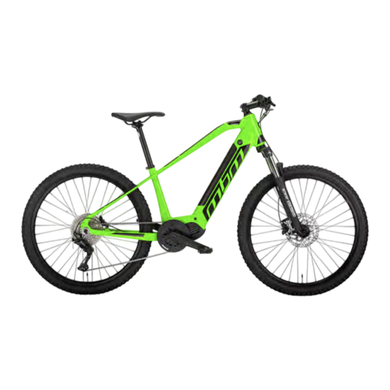
3. BICYCLE DESCRIPTION 3.1 General description The pedal-assisted bicycle is designed and built to be used outdoors, on roads and private or public environments. In particular, the components and the type of pedal-assisted bicycle, allow you to face routes with asphalted and unpaved surfaces without particular roughness. -
Page 10: Data Sheet
3.2 Data sheet CODE E406 FRAME HYDROFORMED ALUMINIUM FORK SUSPENSION WITH ADJUSTMENT CRANKSET 36 TEETH REAR DERAILLEUR DEORE SHIFTER 10 SPEEDS BRAKES SHIMANO MT200 HYDRAULIC SHIMANO DISKS ANT: Ø 180 MM POST: Ø 180 MM WHEELS 26*2,25 SADDLE SELLE BASSANO CHAOS RIGHT AND LEFT STEEL AND POLYMER PEDALS MATERIAL... -
Page 11: Brake Levers
3.3 Brake levers The brake levers (Ref.C – Figure 3) are placed on the handlebars of the pedal-assisted bicycle, near the knobs (Ref. D – Figure 3). These systems make it possible to control the brake disc calipers located near the wheel hubs. The right lever controls the rear brake, the left one the front brake. -
Page 12: Service System Management
3.5 Assistance system management 3.5.1 Commands To manage the assistance system there is a controller on the left side of the handlebar. This device allows you to vary the level of assistance and to view information regarding the path and status of the battery. (Figure 4) Near the left knob of the handlebar are 3 keys that can be used with a short or prolonged press;... -
Page 13: Turning The System On/Off
3.5.2 Turning the system on/off To activate the system, press and hold the power button (Ref. I - Figure 5.1) for 2 seconds. The loading page shows the OLI eBike Systems logo. When switched on, the level is preset to level 3 of assistance. To turn off the assistance system, press and hold the button (Ref. -
Page 14: Support Level Setting
3.5.4. Setting the level of support To increase the level of assistance press the + button (Ref. F - Figure 5.2). To decrease the level of assistance press the button - (Ref. G - Figure 5.2). FIG. 5.2 3.5.5. Service levels LEVEL 0 –... -
Page 15: Graphic Display Interface
3.6 Display graphic interface After turning on, the device's home screen appears. This screen allows you to view the following information: - Battery charge status - Velocity - Level of assistance By pressing the i button (Ref. H - Figure 5.3), you can scroll and view the route information in the corner at the top right of the display. -
Page 16: Walking Assistance Mode
3.7 Walking assistance mode To help the cyclist push the bike manually along the climbs, the system supports the walking assistance mode, which allows you to push the bike up at a maximum speed of 5 km/h without the need to pedal. To activate the walking assistance mode , press and hold the button - (Ref. -
Page 17: Menù
3.8 Menu To access the system menu, press and hold the i button (Ref. H - Figure 5.5). Within the menu the items can be selected by moving with the + and - buttons (Ref. F and G - Figure 5.5). FIG. -
Page 18: Error Codes
3.9 Error codes In the event of an anomaly, the system reports the problem to the user by displaying a danger icon combined with a 4-character code that allows you to trace the type of error. Depending on the type of anomaly, the system may prevent the engine from activating or make it run at reduced power. Where it is indicated "to request assistance", the intervention of a specialized technician OLI eBike Systems is neces- sary. -
Page 19: Problem Solving
0805 EXCESSIVE ENGINE TEMPERATURE. THE ENGINE HAS REACHED A TEMPERATURE ABOVE THE DANGER THRESHOLD. 0806 NON-COMPLIANT PERIPHERAL BUS VOLTAGE. 0808 ROTOR LOCKED. THE ENGINE FAILED TO START DUE TO A MECHANICAL BLOCKAGE OR A PROBLEM WITH THE INTERNAL WIRING OF THE DRIVE UNIT. 0809 BATTERY VOLTAGE IS HIGHER THAN THE MAXIMUM ALLOWED. -
Page 20: Battery
3.11 Battery The bicycle provides pedaling assistance by means of an electric motor powered by the battery placed in the down tube of the frame structure. (Figure 6) 3.11.1 Battery charge status You can view the battery charge status directly on the assistance system management display. - Page 21 For install the battery proceed What Follows: 1. This procedure must be performed without the unlock key ; remove the key if inserted; 2. Align the battery above the oblique pipe of the frame by matching the electrical connector (Ref. P – Figure 8); 1.
-
Page 22: Battery Charging
3.11.3 Battery charging Charging the battery of the pedal-assisted bicycle can be done either with the battery fixed to the frame or with the battery extracted and stored in an environment sheltered. To charge the battery , do the following: 1. -
Page 23: Front Suspension
3.12 Front suspension The pedal-assisted bicycle is equipped with a front suspension system that allows you to dampen the sollecitations caused by the roughness of the route. The suspension model is adjustable by means of special adjustment controls at the top of the fork. -
Page 24: Conditions Of Use And Intended Environment
4. CONDITION OF USE AND INTENDED ENVIRONMENTS 4.1 Intended use The pedal-assisted bicycle is designed and built to be used outdoors, on roads and private or public environments. In particular, the components and the type of pedal-assisted bicycle, allow you to face routes with asphalted and unpaved surfaces without particular roughness . -
Page 25: Improper Uses And Contraindications
4.3 Improper uses and contraindications The actions described below, which obviously cannot cover the entire range of potential possibilities of "misuse" of the pedal-assisted bicycle, are to be considered absolutely Prohibited. PROHIBITED OPERATIONS • The execution of prohibited operations invalidates the warranty; •... -
Page 26: Lifting And Transport
5. LIFTING AND TRANSPORT 5.1 Lifting The weight of the chaos model pedal-assisted bicycle is such that it can be lifted and transported by a person, also be- cause of the overall dimensions. The optimal solution to perform the movement is to grab a handlebar knob and the back of the saddle. CRUSHING AND IMPACT •... -
Page 27: Commissioning
6. COMMISSIONING 6.1 Battery charge Before using the bike for the first time you must charge the battery for at least 8 hours, using the appropriate battery charger supplied. The pedal-assisted bicycle model CHAOS is equipped with an electric motor powered by a 36 V lithium-ion battery. The battery pack is housed in the central part of the frame, inside the oblique pipe. -
Page 28: Preliminary Functional Checks
6.2 Preliminary functional check Before each use, the driver must ensure the safety status of the pedal-assisted bicycle. Therefore, perform the following inspec- tions before riding the pedal-assisted bicycle. 6.2.1 Control devices Check the efficiency and state of charge of the battery. Use in a very cold environment quickly degrades battery efficiency . -
Page 29: Frame, Handlebar And Saddle Position
6.2.4 Frame and saddle position Check that the frame and saddle are fixed correctly and positioned in the most comfortable configuration for the rider for complete control of the bike. Otherwise, before departure, act on the systems for adjusting the position of the saddle. For further information on the regulation please refer to section 2.6.1. -
Page 30: Brake Adjustment
6.2.5 Brake adjustment Before using the pedal-assisted bicycle, adjust the position of the brake levers on the handlebars to obtain a comforta- ble and firm grip of lever and knob during braking. Loosen the screw (Ref. S – Figure 11) and turn the brake lever to the desired position. -
Page 31: Use Of Bicycle
7. USE OF THE BICYCLE The pedal-assisted bicycle has been designed and built for use in open places, with asphalt or dirt surface, for amateur uses. • It can only be used by experienced adults and children; • The use of the pedal-assisted bicycle is not recommended for pregnant women; •... -
Page 32: Use Of Bicycle
7.1 Use of the bicycle Before using the pedal-assisted bicycle in places open to traffic, it is advisable to familiarize yourself with the behavior of the vehicle. The first uses must be made in private environments away from traffic, other cyclists or obstacles of any kind. The driver must adapt the driving speed of the pedal-assisted bicycle to the conditions of the route and the presence of other vehicles or pedestrians. -
Page 33: Maintenance
8. MAINTENANCE 8.1 Generalities RISK OF ACCIDENTS During all maintenance work, follow the appropriate safety measures. All maintenance operations must be carried out with the battery disconnected from the bicycle and the battery charger. The bicycle must be supported in a stable way tak- ing advantage of special support elements. -
Page 34: Weekly Maintenance And Checks
8.2.3 Brake functioning check The brakes must be adjusted in such a way as to ensure effective braking and, at the same time, the control levers must have an adequate stroke to be able to modulate braking: in other words the brakes must not be too slow or too pulled. Check that brake system discs and pads are not contaminated with oils or soaps. -
Page 35: Monthly Maintenance And Checks
8.4 Monthly maintenance and checks 8.4.1 Control of electrical circuits and components Check the condition and fastening of the battery cables: the sheaths of the electrical cables must be in good condition and the terminals must be tightly tightened, not corroded and, if necessary, covered with protective and insulating grease. 8.4.2 Control and adjustment of the rear derailleur Adjustment of the lower and upper limit switches of the gearbox: Turn the two screws (Ref. -
Page 36: Technical Assistance And Spare Parts
9. TECHNICAL ASSISTANCE AND SPARE PARTS If you need technical assistance, please contact your authorized dealer. In case of assembly of non-original parts the warranty loses validity! ORIGINAL SPARE PARTS The manufacturer is exempt from any liability for damages of any kind generated by the use of non-original spare parts. -
Page 37: Components And Materials Disposal
11. COMPONENTS AND MATERIALS DISPOSAL DISPOSAL OF MATERIALS The disposal of packaging, waste and vacuumed dust, replaced parts and / or the pedal-assisted bicycle as a whole at the end of its expected life must be carried out in compliance with the environment avoiding polluting su- olo, water and air and in any case respecting the national and local legislation in force on the subject. -
Page 38: Warranty Rules
12. WARRANTY RULES M.B.M. S.r.l. Unipersonale guarantees that its bicycles are free from any manufacturing or workmanship defects. This warranty covers the repair or replacement of any part recognized to be defective, subject to the following conditions: TERMS AND CONDITIONS •... -
Page 39: Conformity
• Transport costs. Except as provided in this warranty and subject to all other warranties, MBM and its employees and agents will not be liable for loss or damage of any kind (including incidental and consequential losses or damage caused by negligence or failure) originated from or related to any MBM bicycle. - Page 40 M.B.M. S.r.l. Unipersonale Via Emilia Levante, 1671/73/75 | 47521 Cesena (FC) Tel.: + 39 0547 -300364 Fax: +39 0547-304326 Email: info@mbmbike.it...
Need help?
Do you have a question about the CHAOS 26 and is the answer not in the manual?
Questions and answers