Advertisement
Quick Links
Advertisement

Subscribe to Our Youtube Channel
Related Manuals for MBM FUNK URBAN 20


Summary of Contents for MBM FUNK URBAN 20
- Page 1 F U N K U R B A N U S E R M A N U A L F U N K U R B A N 2 0 ”...
- Page 2 I N D E X 1. FOREWORD 4. CONDITION OF USE AND INTENDED ENVIRONMENT 4.1 Intended use 1.1 General 4.2 Environment of use 1.2 Assistance 1. 3Graphic form of security warnings 4.3 Improper uses and contraindications 5. LIFTING AND TRANSPORT 2.
-
Page 3: Table Of Contents
9. TECHNICAL ASSISTANCE AND SPARE PARTS 10. WAREHOUSE 11. DISPOSAL OF COMPONENTS AND MATERIALS 12. WARRANTY RULES 13. CONFORMITY... - Page 4 1.FOREWORD 1.1 Generalities This manual is an integral and essential part of the FUNK URBAN 20” pedal-assisted bicycle. Before commissioning , it is essential that users read, understand and scrupulously follow the following provisions. The manufacturer is not liable for damage caused to persons and / or things or to the pedal-assisted bicycle if it is used incorrectly with respect to the requirements Indicated.
- Page 5 2. SECURITY WARNINGS USE OF THE PEDAL-ASSISTED BICYCLE Each user must first have read the instruction manual, in particular the chapter on safety claims. ATTENTION RISK ASSOCIATED WITH THE USE OF THE PEDAL-ASSISTED BICYCLE • Notwithstanding the application of safety devices, for the safe use of the pedal-assisted bicycle , all the requirements re- lating to the prevention of accidents reported in this manual.
- Page 6 UNAUTHORIZED CHANGES If you hear unusual noises or feel something strange, stop the pedal-assisted bicycle immediately. Carry out a check after- wards and, if necessary, contact the authorized dealer. ATTENTION For any data not included or not deductible from this manual, it is recommended to consult the authorized dealer directly. 2.3 Warnings for users 1.
- Page 7 2.5 Other provisions The first thing to do when starting use is to check the presence and integrity of the protections and the operation of the safety devices. If you find any defects, do not use the pedal-assisted bicycle! GUARDS It is strictly forbidden, therefore, to modify or remove the guards, controls, labels and indication plates.
- Page 8 2.6.2 Handlebar adjustment For a comfortable posture on the bike, which does not cause neck or back pain, we recommend the handlebar column height adjustment. Adjust the height of the handlebar column by operating the quick release mechanism (Ref. C – Figure 2). Check that the mechanism is tight before using the vehicle.
- Page 9 2.6.3 Pedal mounting Right pedal: IT is identified by the letter “R” marked on its pin. For pedal mounting, screw by turning the pin clockwise. (Figure 4). Left pedal: it is identified by the letter “L” marked on its pin. For pedal mounting, screw by turning the pin counterclock- wise (Figure 4).
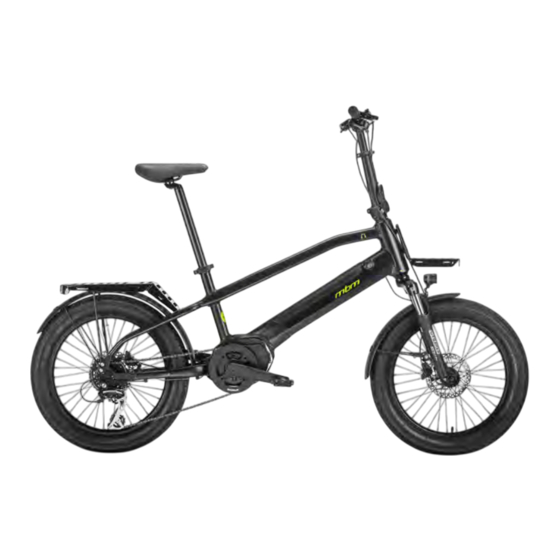
- Page 10 3. BICYCLE DESCRIPTION 3.1 General description The pedal-assisted bicycle is designed and built to be used outdoors, on roads and private or public environments. In particular, the components and the type of pedal-assisted bicycle allow you to tackle routes with asphalt surfaces or with similar characteristics without particular roughness.
- Page 11 8 SPEEDS BRAKES SHIMANO MT 200 HYDRAULIC DISKS SHIMANO RT26 ANT: Ø160MM POST:Ø160MM WHEELS 20*3,0 SADDLE MBM FUNK PEDAL RIGHT AND LEFT IN NON-SLIP POLYMER MATERIAL LIGHTS SPANNINGA 40 LUX ENGINE CENTRAL MOTOR OLI MOVE ONE 60 NM BATTERY SEMI-INTEGRATEDSPARD YT 30240, 36V, 7AH 252 WH...
- Page 12 3.3 Brake levers The brake levers (Ref. F – Figure 5) are placed on the handlebars of the pedal-assisted bicycle, near the knobs (Ref. G – Fig- ure 5). These systems make it possible to control the calipers of the disc brakes located near the wheel hubs. The right le- ver controls the rear brake, the left one the front brake;...
- Page 13 3.5 Assistance system management 3.5.1 Commands To manage the assistance system there is a display on the left side of the handlebar. This device allows you to vary the level of assistance and to view information regarding the path and status of the battery (Figure 6). I - Display;...
- Page 14 3.5.3 Activate support The engine is activated and deactivated immediately if the pedaling stops. The power of the motor depends on the force imposed on the pedals according to a multiplicative factor depending on the level of assistance selected. Press and release the power button (Ref. L - Figure 6) to increase the level of assistance. To decrease the level of assis- tance press and release the “-”...
- Page 15 3.5.5 Single distance reset With the device turned on, press the power button and the “-” button (Ref. L,M - Figure 7.1) at the same time to reset the single distance (TRIP). 3.5.6 Walking assistance mode The pedal-assisted bicycle is equipped with the function of walking assistance. This function allows you to move the bike more easily during manual movement in case you face small climbs.
- Page 16 3.5.8 Battery indicators The state of charge of the battery (Ref.1 - Fig. 7) is indicated on the left side of the display. When the battery is fully charged, 5 bars appear on the display; the bars gradually decrease as the battery discharges. When the battery charge is low the last bar flashes to warn that the battery needs to be recharged.
- Page 17 0106 INADEQUATE RESPONSE OF THE TORQUE SENSOR. THE TORQUE SENSOR IS FAULTY. 0801 FAILURE OF THE MOTOR ROTATION SENSOR. 0802 FAILURE OF THE PEDAL ROTATION SENSOR. CONTROL UNIT TEMPERATURE TOO HIGH. 0804 THE TEMPERATURE SENSOR OF THE CONTROL UNIT DETECTED A TEMPERATURE HIGHER THAN THE PERMISSIBLE LIMIT . 0805 ENGINE TEMPERATURE TOO HIGH.
- Page 18 3.6 Battery The assistance system of the pedal-assisted bicycle, to work, needs the presence of the power battery. Specifically, the battery is removable, so you can take it out for maintenance actions or when you want to store the vehicle. 3.6.1 Battery charge status You can view the battery charge status directly on the assistance system management display.
- Page 19 For install the battery proceed What Follows: 1. This procedure must be performed without the unlock key ; remove the key if inserted; 2. Align the battery above the oblique pipe of the frame by matching the electrical connector (Ref. R – Figure 10); 1.
- Page 20 3.6.3 Battery charging The charging of the pedal-assisted battery can be carried out both with the battery fixed to the frame and with the same extracted and stored in a sheltered environment. To charge the battery , do the following: 1.
- Page 21 3.7 Front and rear light To ensure visibility during both day and night hours, two lights are installed in the FUNK URBAN model, one front (Figure 12) and one rear (Figure 13). For switching on and off the lights, refer to section 3.5.7. FIG.
- Page 22 4. CONDITION OF USE AND INTENDED ENVIRONMENT 4.1 Intended use The pedal-assisted bicycle is designed and built to be used outdoors, on roads and private or public environments. In particular, the components and the type of pedal-assisted bicycle allow you to tackle routes with asphalt surfaces or with similar characteristics without particular roughness .
- Page 23 4.3 Improper uses and contraindications The actions described below, which obviously cannot cover the entire range of potential possibilities of “misuse” of the pedal-assisted bicycle, are to be considered absolutely Prohibited. PROHIBITED OPERATIONS • The execution of prohibited operations invalidates the warranty; •...
- Page 24 5. LIFTING AND TRANSPORT 5.1 Lifting The weight of the PEDAL-assisted bicycle model FUNK URBAN is such that it can be lifted and transported by a person, also because of its overall dimensions. The optimal solution to perform the movement is to grab a handlebar knob and the back of the saddle. CRUSHING AND IMPACT •...
- Page 25 6. COMMISSIONING 6.1 Battery charge Before using the bike for the first time, you must charge the battery for at least 8 hours using the supplied battery charger. The pedal-assisted bicycle, model FUNK URBAN, is equipped with an electric motor powered by a 36V lithium-ion battery. The battery pack is positioned inside the frame in the oblique pipe of the vehicle.
- Page 26 6.2 Preliminary functional checks Before each use, the driver must ensure the safety status of the pedal-assisted bicycle. Therefore, perform the follow- ing inspections before riding the pedal-assisted bicycle. 6.2.1 Control devices Check the efficiency and state of charge of the battery. Use in a very cold environment quickly degrades battery efficien- cy.
- Page 27 6.2.4 Frame, handlebar and saddle position Check that the saddle and handlebars are properly attached to the frame and positioned in the most comfortable config- uration for the rider, for complete control of the bicycle. Otherwise, before departure, act on the systems for adjusting the position of the saddle and handlebars.
- Page 28 6.2.5 Brake adjustment Adjust the brake lever to ensure a firm grip of the handle- bars even during braking. To apply maximum braking power to the lever it is possible to make the following adjustments: - Rotate the brake lever using the clamping screw (Ref. T - Figure 15) until you reach a comfortable position of the hand.
- Page 29 6.2.7 Headlight operation Before using the pedal-assisted bicycle, check that the front and rear lights are working properly. For more information on switching them on and off , please refer to section 3.5.7. 7. USE OF THE BICYCLE The pedal-assisted bicycle has been designed and built for use in open places, with asphalt bottom or similar, for ama- teur use.
- Page 30 7.1 Use of the bicycle Before using the pedal-assisted bicycle in places open to traffic, it is advisable to familiarize yourself with the behavior of the vehicle. The first uses must be made in private environments away from traffic, other cyclists and obstacles of any kind.
- Page 31 8. MAINTENANCE 8.1 General RISK OF ACCIDENTS During all maintenance work, follow the appropriate safety measures. All maintenance operations must be carried out with the battery disconnected from the pedal-assisted bicycle and the battery charger; the bicycle must be supported in a stable manner using special support elements.
- Page 32 8.2.3 Brake operation control The brakes must be adjusted in such a way as to ensure effective braking and, at the same time, the control levers must have an adequate stroke to be able to modulate braking: in other words the brakes must not be too slow or too pulled. Brake adjustment should only be carried out by authorized personnel.
- Page 33 8.4 Monthly maintenance and checks 8.4.1 Control of electrical circuits and components Check the condition and fixing of the battery cables : the sheaths of the electrical cables must be in good condition and the terminals must be tight, not corroded and if necessary covered with protective grease and specific insulation. Check that all light bulbs and lights have been switched on correctly.
-
Page 34: Technical Assistance And Spare Parts
9. TECHNICAL ASSISTANCE AND SPARE PARTS If you need technical assistance, please contact your authorized dealer. In case of assembly of non-original parts, the warranty loses its validity! ORIGINAL SPARE PARTS The manufacturer is exempt from any liability for damages of any kind, generated by the use of non-original spare parts. ATTENTION 10. -
Page 35: Disposal Of Components And Materials
11. DISPOSAL OF COMPONENTS AND MATERIALS DISPOSAL OF MATERIALS The disposal of packaging, waste and vacuumed dust, replaced parts and/or the pedal-assisted bicycle as a whole at the end of its intended life must be carried out in environmental respect, avoiding polluting soil, water and air and respecting in any case the national and local legislation in force on the subject. -
Page 36: Warranty Rules
12. WARRANTY RULES MBM S.r.l. Unipersonale guarantees that its bicycles are free from any manufacturing or workmanship defects. This warranty covers the repair or replacement of any part recognized to be defective, subject to the following conditions: TERMS AND CONDITIONS •... -
Page 37: Conformity
• Transport costs . Except as provided in this warranty and remaining subject to all other warranties, MBM and its employees and agents shall not be liable for loss or damage of any kind (including incidental and consequential losses or damages caused by negligence or deficiency) arising out of or relating to any MBM bicycle. - Page 38 M.B.M. S.r.l. Unipersonale Via Emilia Levante, 1671/73/75 | 47521 Cesena (FC) Tel.: + 39 0547 -300364 Fax: +39 0547-304326 Email: info@mbmbike.it...
Need help?
Do you have a question about the FUNK URBAN 20 and is the answer not in the manual?
Questions and answers