
Related Manuals for M&R Challenger II 12 COLOR


Summary of Contents for M&R Challenger II 12 COLOR
- Page 1 $45.00 The M&R Challenger II mrprint.com M&R Printing Equipment, Inc. www.mrprint.com Toll Free 1-800-736-6431 International +847-967-4461 050605MS MAN-CH2...
- Page 2 IMPORTANT! IMPORTANT! The product described in this publication may employ hazardous voltages or might create other conditions that could, through misuse, inattention, or lack of understanding, result in personal injury, or damage to the product or to other equipment. It is imperative, therefore, that personnel involved in the installation, maintenance, or use of this product understand the operation of the product and the contents of this publication.
- Page 3 Challenger II mrprint.com Product Information Each product manufactured by M&R Printing Equipment, Inc., or one of its subsidiaries, NuArc Company, Inc. or Amscomatic Inc. includes a metal manufactures rating plate permanently fixed to the product as shown above. The Manufacturers Rating Plate includes important information regarding the product, such as elec- trical power requirements, Model No., Serial No.
-
Page 5: Introduction
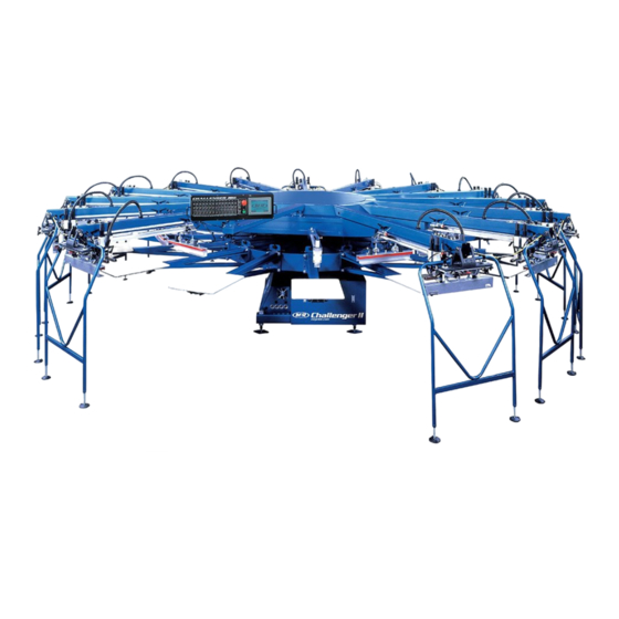
Introduction Valued Customer, Thank you and congratulations on your purchase of your new M&R Challenger Series II semi-auto- matic Textile Screen Printing System. A thorough understanding of the operation and maintenance of your new M&R Challenger Series II will insure maximum production rates and a long service life for your investment. This Operator’s Manual is provided to help guide you, and your employees, in the proper procedures for set-up, operation and preventive maintenance of your new M&R Challenger Series II. -
Page 7: Table Of Contents
Challenger II mrprint.com Table of Disclaimer Contents Model Description Introduction Safety Precautions..........1 Specifications............5 Screen Frame & Image Size........9 Installation Instructions........11 Set Up Instructions/Central Off-Contact....13 Operator Controls..........15 E 300 Operator Interface........25 Preventive Maintenance Procedures....47 Pallet Leveling Procedure........71 Proximity Switch Location........75 Index Lift Cylinder Cushion Adj......78 Idec Relay Location..........79 Trouble Shooting Procedure.......83 Recommended Spare Parts.......87... -
Page 9: Safety Precautions
Challenger II mrprint.com Safety Precautions SAFETY PRECAUTIONS This equipment must be used only for the defined purpose as described in the Operator’s Manual, and must be main- FUNDAMENTAL SAFETY INSTRUCTIONS: tained in perfect running condition in accordance with Please read all information regarding safety precautions described Safety Regulations. - Page 10 Challenger II mrprint.com Safety Precautions This symbol signifies a possible 1. The equipment is shut down. imminent danger for life and health 2. The electrical power has been dis-connected from the persons equipment equipment. Operators. 3. In case of delivery of partial components, the Operator Non-observance these must install safety devices in accordance with regula-...
- Page 11 Challenger II mrprint.com Safety Precautions All pneumatic piping and/or hoses must be checked at reg- 2. Safety guards have been provided to protect the opera- ular intervals for signs of wear or failure. tor from all moving parts. Please do not remove these Safety Guards any time the equipment is in operation.
- Page 12 Challenger II mrprint.com Safety Precautions 3. PRACTICE GOOD HOUSEKEEPING: Maintain and area adjacent to NOT ON the equipment for tool and color stor- age. Clean up all spills and eliminate all potential trip points from the operating areas around the equipment to prevent slipping or falling into the working zone of the equipment.
-
Page 13: Specifications
Challenger II mrprint.com Specifications SPECIFICATIONS CHALLENGER Series II (Pneumatic Models) MODEL No. 12 COLOR 14 COLOR 16 COLOR 18 COLOR Maximum Image Size 20” x 28” (50 x 70 cm) 20” x 28” (50 x 70 cm) 20” x 28” (50 x 70 cm) 20”... - Page 14 Challenger II mrprint.com Specifications SPECIFICATIONS CHALLENGER Series II (AC Models) MODEL No. 12 COLOR 14 COLOR 16 COLOR 18 COLOR Maximum Image Size 20” x 28” (50 x 70 cm) 20” x 28” (50 x 70 cm) 20” x 28” (50 x 70 cm) 20”...
- Page 15 Challenger II mrprint.com Specifications Figure 2 Typical Multiple Unit (Loop) Compressor-Chiller Layout A clean, moisture free compressed air supply is essential for the contin- ued operation of the M&R Challenger Series II press. We strongly recom- mend that a refrigerated air chiller be installed in the compressed air sup- ply line to the Challenger Series II press to prevent moisture damage to pneumatic seals, valves and air cylinders used in the operation of the print carriage (See diagram above).
- Page 16 Challenger II mrprint.com Specifications Figure 1 Typical Compressor-Chiller Layout A clean, moisture free compressed air supply is essential for the contin- ued operation of the M&R Challenger Series II press. We strongly recom- mend that a refrigerated air chiller be installed in the compressed air sup- ply line to the Challenger Series II press to prevent moisture damage to pneumatic seals, valves and air cylinders used in the operation of the print carriage (See diagram above).
-
Page 17: Screen Frame & Image Size
Challenger II mrprint.com Screen Frame & Image Size NOTE: Although every effort has been made to provide accurate screen frame specifications, M&R Printing Equipment, Inc. does not assume any liability for damages, whether consequential or incidental that may result from the use or misuse of the indicated specifications. M&R Printing Equipment, Inc. - Page 18 Challenger II mrprint.com Screen Frame & Image Size Use this chart to determine whether your existing screen frame can be used on the M&R Challenger Series II. 1. Locate where your frames width falls along the left side of the chart. 2.
-
Page 19: Installation Instructions
Challenger II mrprint.com Installation The M&R Challenger Series II requires installation by an • A three-color minimum print job, with tight registration, should be ready to run. Refer M&R factory-trained service representative. The following to page 11 & 12 for the required screen conditions must be addressed before a technician can be frame dimensions and image placement. - Page 20 Challenger II mrprint.com Installation Hardware The hardware list shown below illustrates and describes all hardware required to assemble your Challenger Series II screen printing system. The quantity is indicated for each available model size. Although a Factory Trained M&R Service Representative will perform the original installation of this equipment, this hardware list can prove valuable should the equipment be relocated or dis-assembled for any reason.
-
Page 21: Set Up Instructions/Central Off-Contact
Challenger II mrprint.com General Setup & Registration NOTE: When using the micro- 1. Before installing screens into the print stations, check the registration, you must have the rear recommended print order, consider the mesh count, type of screen frame clamps released to ink, and area (image size) of ink deposit. - Page 22 Challenger II mrprint.com General Setup & Registration The following is a step by step instruction of how to change Each setting is designed to change the off-contact setting the off -contact setting using the central-off-contact lever: by 1/16” (1.5mm). The central off-contact adjustment lever has four possible After determining the proper off-contact setting, lower the positions.
-
Page 23: Operator Controls
Challenger II mrprint.com Operator Controls The Challenger Series II is a blend of exciting technology Main “ON/OFF” switch location. (See figure 1) that incorporates microprocessor controls and a unique Fig. 1 servo driven index system that offer the ultimate in maxi- mum production efficiency. - Page 24 Challenger II mrprint.com Operator Controls A small L.E.D. located in the tip of the toggle handle will The index system will cycle one time, along with any print illuminate confirming activation. When in the “Single” stations that are selected to “ON”. Placing this toggle position the L.E.D.
- Page 25 Challenger II mrprint.com Operator Controls Independent Print Start Push Button: This push button permits manual cycling of a selected print station. Please note that the “Single/Double” toggle switch for the selected print station must be set to either “Single” or “Double”...
- Page 26 Challenger II mrprint.com Operator Controls Test Print Toggle Switch: This toggle switch is designed to aid the system operator when it is desired to print only one garment to check for registration or image quality. When this toggle switch is placed in the “ON” Print Start/Print Finish Toggle Switch: position, the control system will auto- This toggle switch is provided as a...
- Page 27 Challenger II mrprint.com Operator Controls Front/Rear Toggle Switch: This toggle switch permits the system operator to command the selected print station to stop in either the “Front” or “Rear” position. Generally, this switch is used whenever the Operator desires to complete the print cycle with the screen frame flooded with ink, to reduce the chance of ink drying in the image.
- Page 28 Challenger II mrprint.com Operator Controls To lower the index table, press the green “Reset” push but- Individual Print Station Controls: ton (6) located just to the right of the “Print” push button on Each of the print stations used on the M&R Challenger the Print Station control panel.
- Page 29 Challenger II mrprint.com Operator Controls YELLOW CYCLE INTERRUPTION CORDS/BARRIER WARNING! NEVER ATTEMPT TO GATES: BY-PASS OR DEFEAT ANY CONTROL To prevent injury to operating personnel, yellow cycle inter- DEVICE OR APPLIANCE. CHECK TO ruption cords, or on some models, yellow barrier gates are SURE THAT CONTROL...
- Page 30 Challenger II mrprint.com Operator Controls DO NOT STAND BETWEEN INDEX PALLET SUPPORT ARMS TO INSTALL SCREEN FRAMES, ADJUST SCREEN REGISTER OR PERFORM ANY OTHER OPERATIONAL ADJUSTMENTS WITH THE YELLOW BARRIER GATES CON- NECTED! WARNING! AC Print Station Drive Inverter - While adjusting either the flood bar or squeegee stroke speed, observe the L.E.D.
- Page 31 Challenger II mrprint.com Operator Controls When the screen frames are properly loaded into the front a slight pressure felt on the bottom of the screen mesh. To and rear screen frame holders, lock the screen frame into increase the flood bar pressure, turn the black knurled position using the pneumatic screen frame clamp toggle knobs counterclockwise.
- Page 32 Challenger II mrprint.com Operator Controls NOTE: DO NOT ADJUST THE SEN- SOR WHILE THE PRINT STATION IS IN OPERATION! IMPORTANT! The squeegee and flood bar speeds may be independently adjusted to suit a wide range of print applications or require- ments.
-
Page 33: E 300 Operator Interface
Challenger II mrprint.com May 2005 E 300 Operator Interface E 300 OPERATOR INTERFACE - The Operator Interface control panel is divided into 5 differ- ent control areas as follows. (See Figure 1 at the right) a. Along the top width of the control are status L.E.D. indi- cators each of which can display either a green or red indi- cation based on the various operational parameters listed below each individual indicator. - Page 34 Challenger II mrprint.com May 2005 E 300 Operator Interface L.E.D. STATUS INDICATOR LIGHTS - INDEX DELAY - This indicator light displays a green L.E.D. when the system is operating with the "Index Delay" command. A red L.E.D. will be displayed when the system is operating in the "Revolver"...
- Page 35 Challenger II mrprint.com May 2005 E 300 Operator Interface OPERATIONAL CONTROL & STATUS KEYS - MAIN SCREEN The first screen which is displayed is the MAIN SCREEN. The L.C.D window will display a graphic representation of the M&R Challenger Series II press. In the lower right corner of the L.C.D.
- Page 36 Challenger II mrprint.com May 2005 E 300 Operator Interface Now press the "Return/Enter" key to enter the number of print cycles into the PLC. Left Counter The next sub-menu selection is "Left Counter". The "Left Counter" sub-menu displays the number of print cycles which remain in the "Set Counter"...
- Page 37 Challenger II mrprint.com May 2005 E 300 Operator Interface The flashing frame should be located on the Index Dwell Time indication already. If it is not, use the “Arrow” keys to place it on the indication. The maximum dwell time allowed is "20"...
- Page 38 Challenger II mrprint.com May 2005 E 300 Operator Interface Print Up/Down", "Skip T-Shirt/Sensor", "InkDip Every", "Glue Applicator" and ">Servo Index Options". M&R REVOLVER SEQUENCING PROGRAM (Optional) (U.S. Patent No. 5,595,113) The first sub-menu item is "Revolver mode". NOTE: The "REVOLVER" option only appears on presses equipped with the "REVOLVER"...
- Page 39 Challenger II mrprint.com May 2005 E 300 Operator Interface Press the "ARROW DOWN" key one time, then press the "ARROW RIGHT" key one time to access the "Enter Program" menu item. This control function is used to enter print sequences for the Revolver program mode of opera- tion.
- Page 40 Challenger II mrprint.com May 2005 E 300 Operator Interface Flash: The next menu item in the "OPTIONS" menu is "FLASH". This menu item provides a visual indication which alerts the system Operator as to which print heads are currently selected for "Flash Cure" operation. Print heads are displayed from the left to the right of the dis- play screen starting with the highest number print head.
- Page 41 Challenger II mrprint.com May 2005 E 300 Operator Interface Now press the "RETURN/ENTER" key. The number indica- tion for the print cycles will change indicating the selected print station will now perform multiple flood/print strokes in the "Multi-Print" mode. To return a print station to standard (single) print operation, locate the flashing cursor on the number indicator under the print station and press the num- ber "1"...
- Page 42 Challenger II mrprint.com May 2005 E 300 Operator Interface Pressing the "Print" push button once again will command the squeegee in the selected print station to chop down to the print position. This allows the press Operator to easily check and adjust squeegee pressure prior to printing.
- Page 43 Challenger II mrprint.com May 2005 E 300 Operator Interface Skip: No T-Shirt/Sensor: (US Patent No. 5,383,400) The next menu selection under "OPTIONS" is "Skip" sensor. This menu item is used to activate the "NO SHIRT DETEC- TOR" option. Activation of the "NO SHIRT DETECTOR" option may be accomplished in two ways.
- Page 44 Challenger II mrprint.com May 2005 E 300 Operator Interface Glue Applicator: The "GLUE APPLICATOR" sub-menu provides control adjustments for the optional M&R Annamister Automatic Adhesive Application system. The available parameters are "Spray 1 Revltn Only:" ,"Spray Every: Revolution" "Front Delay", "Front Duration", Rear Delay", "Rear Duration", "Revolution #:"...
- Page 45 Challenger II mrprint.com May 2005 E 300 Operator Interface Press the “RIGHT ARROW” key one time to access the “Front Duration” dwell time. This sub-menu item permits the adjustment of the time duration in which the front air valve which operates the front spray gun is activated. This adjustment, like the “Front Delay”...
- Page 46 Challenger II mrprint.com May 2005 E 300 Operator Interface You will note that across the bottom of the display screen is a dark bar with “TIMERS”, “Midas/MStamp”, “TESTS”, “MPR”, “Manual Glue”, “Pg Dwn” and “Pg Up”. Except for “Midas/MStamp” and “Pg Dwn” and “Pg Up” these functions work as explained previously.
- Page 47 Challenger II mrprint.com May 2005 E 300 Operator Interface Midas Loader” “Mega-Stamp Connected/Not Connected” are used to activate these options in the PLC program. To turn these options “On”, use the “Arrow” keys to place the flashing cursor on the “Connected/Not Connected”...
- Page 48 Challenger II mrprint.com May 2005 E 300 Operator Interface Now press the "ENTER" key and hold it down until the desired numerical value, either plus or minus is displayed. Then release the "ENTER" key. Your selection is now pro- grammed into the Servo Drive Offset. Press the buttons below “Pg Dwn”...
- Page 49 Challenger II mrprint.com May 2005 E 300 Operator Interface As you select either "ON" or "OFF" the various switches and push buttons used to control the system, the particular switch or push button will become highlighted on the graph- ic representation of the control panel, indicating that it is working properly.
- Page 50 Challenger II mrprint.com May 2005 E 300 Operator Interface OTHER TESTS This menu selection is used to display the current opera- tional status of other control features which may be utilized on the equipment. These control features include Print head push buttons, Yellow cycle interruption cords, no t-shirt sen- sor, Foot Pedal, Air Pressure Switch and PLC Errors.
- Page 51 Challenger II mrprint.com May 2005 E 300 Operator Interface To enter the current year, press the "9" key, then press the "8" key. Now press the "ENTER" key. The day of the week will automatically be displayed based on the information entered for month, date and year.
- Page 52 Challenger II mrprint.com May 2005 E 300 Operator Interface MAIN MENU SCREEN REVOLVER MODE PLC Identity No. COUNTERS >Revolver Mode: Program Version No. Shift Counter >Index Delay: MTA No. Job Counter >Wait Set Counter >Enter Program Left Counter Revolution No.: Total Counter 181716151413121110987654321 Speed (Doz/hour)
- Page 53 Challenger II mrprint.com May 2005 E 300 Operator Interface MAIN MENU SCREEN PLC Identity No. Program Version No. MTA No. SERVO DRIVE TEST Regenerative load ratio: Effective load ratio: Peak load ratio: HARDWARE TEST Motor Rotational Speed: 0.0 rpm >Panel Test Actual Present: 0 pls >Proximities Test...
- Page 54 Challenger II mrprint.com May 2005 E 300 Operator Interface MAIN MENU SCREEN PLC Identity No. Program Version No. MTA No. MPR DATA Job No. Message Code SERVICE DATA DATE AND TIME M&R INFO M&R Printing Equipment, Inc. - Glen Ellyn, Illinois...
-
Page 55: Preventive Maintenance Procedures
PREVENTIVE MAINTENANCE PROCEDURE CHALLENGER Series II PREVENTIVE MAINTENANCE PROCEDURES - The benefits of a regularly scheduled preventive maintenance program can never be over-estimated. Equipment which is prop- erly maintained operates more efficiently, extends service life and reduces operating costs. A properly managed preventive mainte- nance program will minimize downtime and its attendant costs before they occur, allowing you to be your most productive. - Page 56 PREVENTIVE MAINTENANCE PROCEDURE CHALLENGER Series II 4. When preventive maintenance procedures are complete ed, open the manual shut off valve to restore com- pressed air to the equipment. The manual shut off valve is in the “Open” position as shown in Fig. 4 at the right. (See top illustration at the right) 5.
- Page 57 PREVENTIVE MAINTENANCE PROCEDURE CHALLENGER Series II Bulletin No. PH1 The frequency of the following preventive maintenance procedure is based on a 8 hour daily production shift or 40 hour work week. Maintenance Point Check and clean away as needed any lint, ink or spray adhesive which may have accumulated on the print carriage assembly.
- Page 58 PREVENTIVE MAINTENANCE PROCEDURE CHALLENGER Series II Bulletin No. EL1 The frequency of the following preventive maintenance procedure is based on a 8 hour daily production shift or 40 hour work week. Maintenance Point Check and clean as required the lower electrical component enclosure air vents and circulation fan of any accumula- tion of lint or dirt.
- Page 59 PREVENTIVE MAINTENANCE PROCEDURE CHALLENGER Series II Bulletin No. IX1 The frequency of the following preventive maintenance procedure is Maintenance Point based on a 8 hour daily production shift or 40 hour work week. Check moisture trap and drain as needed. In normal operation, you should never notice any accumulation of water in the moisture trap.
- Page 60 PREVENTIVE MAINTENANCE PROCEDURE CHALLENGER Series II Bulletin No. IX2 Maintenance Point Lubricate indexer assembly bearing using Permatex Super Lube with Teflon. (M&R Part No. 7018031) Frequency Interval Every Day Procedure Information Tools required: 1 - Permatex Super Lube M&R Part No. 7018031 1 - Standard pump action grease gun.
- Page 61 PREVENTIVE MAINTENANCE PROCEDURE CHALLENGER Series II Bulletin No. IX3 The frequency of the following preventive maintenance procedure is based on a 8 hour daily production shift or 40 hour work week. Maintenance Point Check (Vactra) oil level and inspect index drive screw lubrication system for proper operation. Frequency Interval Every Day Procedure Information...
- Page 62 PREVENTIVE MAINTENANCE PROCEDURE CHALLENGER Series II Bulletin No. IX3 Procedure Information (Cont.) 4. The frequency of lubrication may be adjusted through the use of the E 300 Operator Interface on the main control panel. Press the “OPTIONS” key. Now use the “ARROW DOWN”...
- Page 63 PREVENTIVE MAINTENANCE PROCEDURE CHALLENGER Series II Bulletin No. IX4 The frequency of the following preventive maintenance procedure is Maintenance Point based on a 8 hour daily production shift or 40 hour work week. Check air line lubricator/moisture trap assembly oil level. Add 10 wt. non-detergent oil as needed. Oil should be added whenever the graduated sight glass indicator displays a half full indication.
- Page 64 PREVENTIVE MAINTENANCE PROCEDURE CHALLENGER Series II Bulletin No. IX5 The frequency of the following preventive maintenance procedure is based on a 8 hour daily production shift or 40 hour work week. Maintenance Point The air line lubricator automatically dispenses 10 wt. non-detergent oil into the compressed air used to operate the system.
- Page 65 PREVENTIVE MAINTENANCE PROCEDURE CHALLENGER Series II Bulletin No. IX6 The frequency of the following preventive maintenance procedure is based on a 8 hour daily production shift or 40 hour work week. Maintenance Point Lubricate the center index shaft bearings using white lithium grease M&R Part No. 7018017. Frequency Interval Every 16 hours of operation Procedure Information...
- Page 66 PREVENTIVE MAINTENANCE PROCEDURE CHALLENGER Series II Bulletin No. PH2 The frequency of the following preventive maintenance procedure is based on a 8 hour daily production shift or 40 hour work week. Maintenance Point (Pneumatic) Clean away old lubricant and apply a fresh coat of 1/3 white lithium grease (M&R Part No. 7018017) and 2/3 non- detergent oil (M&R Part No.
- Page 67 PREVENTIVE MAINTENANCE PROCEDURE CHALLENGER Series II Bulletin No. PH3 The frequency of the following preventive maintenance procedure is based on a 8 hour daily production shift or 40 hour work week. Maintenance Point (AC Drive Print Stations Only) Lubricate the print carriage assembly linear bearing using Permatex Super lube with Teflon (M&R Part No. 7018031) Frequency Interval Weekly Procedure Information...
- Page 68 PREVENTIVE MAINTENANCE PROCEDURE CHALLENGER Series II Bulletin No. IX7 The frequency of the following preventive maintenance procedure is Maintenance Point based on a 8 hour daily production shift or 40 hour work week. Lubricate the lower carousel plate with white lithium grease (M&R Part No. 7018017) at the point where the index table lift cylinder pistons make contact with the plate.
- Page 69 PREVENTIVE MAINTENANCE PROCEDURE CHALLENGER Series II Bulletin No. PH4 The frequency of the following preventive maintenance procedure is based on a 8 hour daily production shift or 40 hour work week. Maintenance Point Clean away old grease, dirt or lint and apply a fresh coat of 10 wt. non-detergent oil (M&R Part No. 7017000) to the print carriage stroke cylinder (Tol-O-Matic band cylinder) on each print station.
- Page 70 PREVENTIVE MAINTENANCE PROCEDURE CHALLENGER Series II Bulletin No. PH5 The frequency of the following preventive maintenance procedure is Maintenance Point based on a 8 hour daily production shift or 40 hour work week. Clean away old grease dirt or lint and apply a fresh coat of white lithium grease (M&R Part No. 7018017) to the inside “U”...
- Page 71 PREVENTIVE MAINTENANCE PROCEDURE CHALLENGER Series II Bulletin No. IX8 The frequency of the following preventive maintenance procedure is based on a 8 hour daily production shift or 40 hour work week. Maintenance Point Clean away old grease from the inside of the “U” shaped registration forks and each of the registration cam follower bearings on the index table.
- Page 72 PREVENTIVE MAINTENANCE PROCEDURE CHALLENGER Series II Bulletin No. PH6 The frequency of the following preventive maintenance procedure is Maintenance Point based on a 8 hour daily production shift or 40 hour work week. Lubricate the micro-registration threaded adjustment shafts on each print stations front and rear screen frame holder assembly.
- Page 73 PREVENTIVE MAINTENANCE PROCEDURE CHALLENGER Series II Bulletin No. IX9 The frequency of the following preventive maintenance procedure is based on a 8 hour daily production shift or 40 hour work week. Maintenance Point Drain accumulated water and moisture from your compressor receiver tank and the press air manifold located on the bottom of the indexer chassis.
- Page 74 PREVENTIVE MAINTENANCE PROCEDURE CHALLENGER Series II Bulletin No. IX10 The frequency of the following preventive maintenance procedure is based on a 8 hour daily production shift or 40 hour work week. Maintenance Point Replace air filter element in air line moisture trap assembly. Frequency Interval Every Six Months Procedure Information...
- Page 75 PREVENTIVE MAINTENANCE PROCEDURE CHALLENGER Series II Bulletin No. PH7 The frequency of the following preventive maintenance procedure is based on a 8 hour daily production shift or 40 hour work week. Maintenance Point (AC Print Stations Only) Check and adjust as required, the print carriage timing belt tension on each of the print stations. Frequency Interval Every Six Months Procedure Information...
- Page 76 PREVENTIVE MAINTENANCE PROCEDURE CHALLENGER Series II Bulletin No. EL3 The frequency of the following preventive maintenance procedure is based on a 8 hour daily production shift or 40 hour work week. Maintenance Point The service life of the battery in the Mitshubishi PLC unit is three years. When the battery is nearly discharged the “ALARM”...
- Page 77 PREVENTIVE MAINTENANCE PROCEDURE CHALLENGER Series II Bulletin No. EL4 The frequency of the following preventive maintenance procedure is based on a 8 hour daily production shift or 40 hour work week. Maintenance Point The service life of the battery in the Mitshubishi Servo Amplifier Unit is three years. Replace the battery (M&R Part No.
- Page 78 PREVENTIVE MAINTENANCE LOG CHALLENGER Series II The benefits of a regularly scheduled preventive maintenance program can never be over-estimated. Equipment which is properly maintained operates more efficiently, prolongs service life and reduces operating costs. A prop- erly managed preventive maintenance program will minimize downtime and its attendant costs before they occur. Documentation of preventive maintenance procedures performed on your equipment can prove an invaluable ref- erence in the future.
-
Page 79: Pallet Leveling Procedure
Leveling the Pallets LEVELING THE PALLETS: Fig. 3 1. Make sure the print station being used to level the pallets is level by placing a small magnetic level (Torpedo Level) on the chrome plated plate (See Fig. 1). Fig. 1 3. - Page 80 Challenger II mrprint.com Leveling the Pallets After doing this, unplug the air line located on the back of NOTE: If your machine has the “Central - Off Contact the head (Tol-O-Matic Brass Cylinder Fitting). Use a brass Lever”, make sure it is set for the highest position, least fitting union with plug , to plug the air line.
- Page 81 Challenger II mrprint.com Leveling the Pallets NOTES: 10. Now bring the pallet back up and move the head back and forward, (by hand), and adjust the base pallet frame so that surface of the pallet is one business card (.010") from the edge of the flood bar, throughout the length of the print stroke of the head.
- Page 82 Challenger II mrprint.com Leveling the Pallets NOTES: M&R Printing Equipment, Inc. - Glen Ellyn, Illinois...
-
Page 83: Proximity Switch Location
Challenger II mrprint.com Proximity Switch Location & Function INDEX TABLE UP PROXIMITY SWITCH - (Lift “ON” Prox) L.E.D. Indicator This proximity switch is mounted to a bracket located in the middle area of the indexer assembly. The function of this proximity switch is to signal the PLC that the index table has reached its fully raised, or print position. - Page 84 Challenger II mrprint.com Proximity Switch Location & Function DOUBLE INDEX PROXIMITY SWITCH - The function of this proximity switch is to signal the PLC that the double index fork is “dis-engaged” from the index table. A small L.E.D. on the switch illuminates confirming switch operation and the position of the double index fork.
- Page 85 Challenger II mrprint.com Proximity Switch Location & Function HOME PROXIMITY SWITCH - This proximity switch is used during the initial installation Home Proximity Switch and set-up of your M&R Challenger Series II press. The Home proximity switch is used in conjunction with the Index Servo Drive to “teach”...
-
Page 86: Index Lift Cylinder Cushion Adj
Challenger II mrprint.com Proximity Switch Location & Function INDEX DRIVE PROXIMITY SWITCHES - Lower Limit/Reverse Snap Action Switch (“A”) “B” Home Position Proximity Switch (“B”) Upper Limit/Forward Snap Action Switch (“C”) “A” “C” Index Lift Cylinder Cushion Adjustments Adjustments for the deceleration or cushioning of the index table lift/lower cycle are provided on both of the index lift air cylinders. -
Page 87: Idec Relay Location
Challenger II mrprint.com Idec Relay Identification Idec Relay Location & Function K2 (Emergency Relay) - This relay is used to confirm the closure of the red emergency stop push button located on the Operator’s control panel. If this relay does not energize, it is an indication that the red emergency stop push button has been activated (pushed “IN”). - Page 88 Challenger II mrprint.com Idec Relay Identification NOTES:...
- Page 89 Challenger II mrprint.com E 300 Alarm Message Listing ALARM LIST FOR THE CHALLENGER SERIES II WITH THE MITSUBISHI PLC AND SERVO DRIVE, AND THEIR DEFINITIONS. EMERGENCY-PANEL. – This alarm will appear if the Emergency stop push button on the control panel is pushed “IN”.
- Page 90 Challenger II mrprint.com E 300 Alarm Message Listing SRVO AMPLIFIER ALARM. - This alarm will appear if there is an error on the servo amplifier, you must check the read-out on the face of the servo amplifier to see which code is given, this way the source of the problem can be determined.
-
Page 91: Troubleshooting Procedure
Challenger II mrprint.com Troubleshooting Procedure The following information is provided as a guide for troubleshooting in the event a problem may occur during the operation of your M&R Challenger Series II press. Should you have any questions regarding the installation, oper- ation or preventive maintenance procedures for this equipment, we strongly encourage you to contact our Equipment Service Department at 1 (630) 858-6101 during normal business hours, or our 24 hour Emergency Service hotline at 1 (630) 462-4715 in the evening, week ends or holidays. - Page 92 Challenger II mrprint.com Troubleshooting Procedure PROBLEM PROBABLE CAUSE/SOLUTION (Cont.) 4. Index “ON” proximity switch has failed or is mis-adjusted. Check to see if the small Electrical power is indicated to con- L.E.D. on the side of the proximity switch illuminates when the index cam follower trols, but nothing operates.
- Page 93 Challenger II mrprint.com Troubleshooting Procedure PROBLEM PROBABLE CAUSE/SOLUTION Indexer shudders or is excessively 1. The main index shaft bearings require lubrication. Lubricate the index shaft bearing noisy when cycling up or down. with white lithium grease. There are two zerk grease fittings provided on the center index shaft for this purpose.
- Page 94 Challenger II mrprint.com Troubleshooting Procedure PROBLEM PROBABLE CAUSE/SOLUTION In the automatic mode the press 1.The center proximity switch is loose or not making contact. Push the Emergency stop cycles a few times and then stops. push button. Check to see if the proximity switch mounted to the underside of the print station support arm is loose.
- Page 95 Challenger II mrprint.com R R e e c c o o m m m m e e n n d d e e d d S S p p a a r r e e P P a a r r t t s s Part No.
- Page 96 Challenger II mrprint.com R R e e c c o o m m m m e e n n d d e e d d S S p p a a r r e e P P a a r r t t s s Part No.
- Page 97 Challenger II mrprint.com R R e e c c o o m m m m e e n n d d e e d d S S p p a a r r e e P P a a r r t t s s Part No.
- Page 98 Challenger II mrprint.com R R e e c c o o m m m m e e n n d d e e d d S S p p a a r r e e P P a a r r t t s s Part No.
- Page 99 Challenger II mrprint.com R R e e c c o o m m m m e e n n d d e e d d S S p p a a r r e e P P a a r r t t s s Part No.
- Page 100 Challenger II mrprint.com R R e e c c o o m m m m e e n n d d e e d d S S p p a a r r e e P P a a r r t t s s Part No.
-
Page 101: Replacement Parts
Challenger II mrprint.com R R e e p p l l a a c c e e m m e e n n t t P P a a r r t t s s Operator Control Console Part Description Part Number Push Button Switch 1017159... - Page 102 Challenger II mrprint.com R R e e p p l l a a c c e e m m e e n n t t P P a a r r t t s s Lower Index Electrical Cabinet Description M&R Part No.
- Page 103 Challenger II mrprint.com R R e e p p l l a a c c e e m m e e n n t t P P a a r r t t s s PLC Rack 12 and 14 Color Reference No.
- Page 104 Challenger II mrprint.com R R e e p p l l a a c c e e m m e e n n t t P P a a r r t t s s PLC Rack 16 Color Reference No. Description M&R Part No.
- Page 105 Challenger II mrprint.com R R e e p p l l a a c c e e m m e e n n t t P P a a r r t t s s PLC Rack 18 Color Reference No. Description M&R Part No.
- Page 106 Challenger II mrprint.com R R e e p p l l a a c c e e m m e e n n t t P P a a r r t t s s Line Filters Part Name Part Number AC Line Filter 1036020A M&R Printing Equipment, Inc.
- Page 107 Challenger II mrprint.com R R e e p p l l a a c c e e m m e e n n t t P P a a r r t t s s Indexer Electrical Enclosure Part Name Part Number Contactor 3RT1035 230 Volt Models 1011516...
- Page 108 Challenger II mrprint.com R R e e p p l l a a c c e e m m e e n n t t P P a a r r t t s s 12 Color Circuit Breakers Reference No. Description M&R Part No.
- Page 109 Challenger II mrprint.com R R e e p p l l a a c c e e m m e e n n t t P P a a r r t t s s 14 Color Circuit Breakers Reference No. Description M&R Part No.
- Page 110 Challenger II mrprint.com R R e e p p l l a a c c e e m m e e n n t t P P a a r r t t s s 16 Color Circuit Breakers Reference No. Description M&R Part No.
- Page 111 Challenger II mrprint.com R R e e p p l l a a c c e e m m e e n n t t P P a a r r t t s s 18 Color Circuit Breakers Reference No. Description M&R Part No.
- Page 112 Challenger II mrprint.com R R e e p p l l a a c c e e m m e e n n t t P P a a r r t t s s Power Supply & Relays Reference No. Description M&R Part No.
- Page 113 Challenger II mrprint.com R R e e p p l l a a c c e e m m e e n n t t P P a a r r t t s s Accessory Plugs Reference No. Description M&R Part No.
- Page 114 Challenger II mrprint.com R R e e p p l l a a c c e e m m e e n n t t P P a a r r t t s s AC Print Station Control Panel Part Description Part Number Air Lock Valve for Squeegee/Fld Bar...
- Page 115 Challenger II mrprint.com R R e e p p l l a a c c e e m m e e n n t t P P a a r r t t s s Servo Index Drive Lubrication Assembly Reference No.
- Page 116 Challenger II mrprint.com R R e e p p l l a a c c e e m m e e n n t t P P a a r r t t s s Print Station Drive Assembly (110104) Reference No.
- Page 117 Challenger II mrprint.com R R e e p p l l a a c c e e m m e e n n t t P P a a r r t t s s Print Station Inverter Unit Reference No. Description M&R Part No.
- Page 118 Challenger II mrprint.com R R e e p p l l a a c c e e m m e e n n t t P P a a r r t t s s Regulator, Lubricator Moisture Trap Assembly Reference No.
- Page 119 R R e e p p l l a a c c e e m m e e n n t t P P a a r r t t s s Chopper Cylinder Air Valves Reference No. Description M&R Part No. 12 Color Valve Block 2010049A 14 Color Valve Block...
- Page 120 R R e e p p l l a a c c e e m m e e n n t t P P a a r r t t s s M&R Printing Equipment, Inc. Glen Ellyn, Illinois 60137 U.S.A.
- Page 121 Challenger...
- Page 123 Replacement Parts Base Assembly Ref. No. Description M&R Part Number Lift Cylinder 6" Bore 2" Stoke ....... . .2009302 Off-Contact Down Plate #1 .
- Page 124 Replacement Parts Base Assembly Ref. No. Description M&R Part Number Z-Bar Mounting Bracket (12 Color) ......9150858 Z-Bar Mounting Bracket (14 Color) .
- Page 125 Replacement Parts Base Assembly Ref. No. Description M&R Part Number Button Socket Cap Screw 10 - 24 x 1/2" ......3001013 Machine Screw Washer ZP #10 .
- Page 126 Replacement Parts Base Assembly Ref. No. Description M&R Part Number Fin. Hex Nut ZP 3/8" - 16 ........3013007 Split Lock Washer ZP 3/8"...
- Page 127 NEW BALL SCREW INDEX DRIVE ASSEMBLY (Revised 12/27/00)
- Page 132 Challenger...
- Page 134 Replacement Parts Print Head Assembly Ref. No. Description M&R Part Number Kipp Elisa Male Knob 5/16" - 18 .......3032002 Fin.
- Page 135 Replacement Parts Print Head Assembly Ref. No. Description M&R Part Number Button Socket Cap Screw 3/8" - 16 x 1" Lg......3001006 Front Stroke Adjustment Bracket .
- Page 136 Replacement Parts Print Head Assembly Ref. No. Description M&R Part Number Knob, Lg. Cross 3/8" - 24 ........3033000 Threaded Rod ZP 3/8"...
- Page 137 Replacement Parts Print Head Assembly Ref. No. Description M&R Part Number Keylocking Insert 3/8" 16 ........3013106 Leveling Foot Valve Guide 5/8"...
- Page 170 Glossary: active size - The speed at which the servo index drive will make the machine carousel turn, determined by the pallet size selected. adjuster - The mechanism used to change, so as to adjust speed, height, distance and etc. adjustment knob - A knob/handle provided with threads which is used to make changes to speed, height, dis- tance etc.
- Page 171 exposure unit master frame The assembly used to secure the screen during the exposure time. flash mode The condition in which a print station (or print stations) will operate as a flash cure station. flash panel The infra-red panel, powered by electricity, used to create heat to cure inks on a garment. film register pin bar A flat metal strip with three (3) machined dowel pins used to secure pre-punched plas- tic carrier sheets for the placing of film positives or art work.
- Page 172 latch clamp The mechanical device used to join the front screen holder assembly against the head front end plate. L.C.D. The liquid crystal display. locking cam A machined cam milled in such a fashion as to lock two mechanical surfaces against one anoth- er when turned in a specific direction.
- Page 173 press manifold The holding tank under the machine, which will store compressed air, available for the machine to use. prime position The ideal location of placement of different components so that maximum adjustment can be achieved. print finish The function of the machine that will allow the press operator to sequentially shut off the print heads as the last garment gets printed.
- Page 174 squeegee blade The flat thin structural member made of a rubber-like material, used to push the ink through the screen. squeegee pressure The amount of force placed on the squeegee blade to push ink though the screen. stop blocks A solid piece of metal having one or more flat sides, which will be used to determine the place- ment of the screen.
- Page 176 LIMITED WARRANTY M&R TEXTILE EQUIPMENT Textile screen printing equipment manufactured by M&R Printing Equipment, Inc. (“M&R”) is warranted against defects in workmanship and materials provided that it is properly maintained and operated under normal use for a period of two years from the date of shipment.
Need help?
Do you have a question about the Challenger II 12 COLOR and is the answer not in the manual?
Questions and answers