Table of Contents
Advertisement
Advertisement
Table of Contents

Related Manuals for M&R i-Image S


Summary of Contents for M&R i-Image S
- Page 1 S Bv2 Part # MAN-i-Image S V.120617...
-
Page 3: Table Of Contents
Network and Internet Connections ....................12 4.1.4 Power Box ............................ 13 Operation Machine Operation ........................... 14 Main Control Panel - i-Image S ........................ 15 5.2.1 Printer Control Panel ........................16 Tri-Sync Bypass Switch ........................... 17 Startup ..............................17 Shutdown ..............................18 Printer Control Software (PCS) ........................ -
Page 4: Safety And Operational Guidelines
V.120617 1. Safety and Operational Guidelines DANGER This symbol identifies situations that endanger people, property, and/or equipment. If such conditions exist, the equipment must be shut down and all energy sources (electrical, gas, and pneumatic) must be disconnected, purged, and locked out until the problem is resolved. Never attempt to bypass or defeat any safety device. -
Page 5: Management Responsibilities
V.120617 1.1 Management Responsibilities Ensure that this equipment is used only for the purposes set forth in the “Defined Purpose” section of this manual. Ensure that all employees involved with the operation of this equipment or working near it read, understand, and act in accordance with the operational and safety standards set forth in this manual, including the Operator Responsibilities listed below. -
Page 6: Operator Responsibilities
V.120617 1.2 Operator Responsibilities Note: 'Operator Responsibilities' pertain to all employees who work on or near the equipment; this includes, but is not limited to those who clean, maintain and repair the equipment as well as those who operate it. In general, all those who work on or near the equipment have a duty to use reasonable and ordinary care for their own safety when in the vicinity of the machine. -
Page 7: General Information
V.120617 2. General Information This Document This document is based on information available at the time of its publication. While every effort has been made to be accurate, the information contained herein does not purport to cover all details or variations in hardware, software, features, or specifications, or to provide for every possible contingency in connection with installation, operation and maintenance. -
Page 8: Service And Parts
V.120617 2.1 Service and Parts Manufacturer's Rating Plate Most products manufactured by the M&R Companies have a metal manufacturer's rating plate. Below is a label imprinted with the information from your product's rating plate. Please be prepared to provide this information when calling. -
Page 9: Defined Purpose
V.120617 2.2 Defined Purpose Textile Presses Textile Presses are designed to print textile inks on textile substrates, as more fully set forth in the manual specific to that product. Any other use of this equipment is not permitted. Textile Dryers Textile Dryers are designed to cure/dry textile inks on textile substrates, as more fully set forth in the manual specific to that product. -
Page 10: Warranty
V.120617 2.3 Warranty Limited Warranty Your Warranty does not apply to damages sustained due to equipment misuse, whether intentional or negligent, and such misuse may void your warranty. Misuse includes - but is not limited to - the items listed below. In addition, M&R Printing Equipment, Inc. -
Page 11: Specification
V.120617 3. Specification Specifications i-Image S Electrical Requirements 1 2,3 208/230 V, 1 ph, 5 A, 50/60 Hz, 1.15 kW Industrial Printheads Maximum Image Area 51 x 66 cm (20" x 26") Maximum Screen Frame Profile 4.1 cm (1.63") Maximum Screen Frame Size 66 x 91 cm (26"... -
Page 12: Assembly And Setup
4.1.1 Site Preparation The i-Image S unit is intended to be set up and installed by factory trained service technicians. Any moving of the unit after installation and calibration may affect the printers quality. It is highly recommended the final position and location of the machine be determined at the time of installation. -
Page 13: Power Box
V.120617 4.1.4 Power Box Plug cord (2) from Power Box (1) into On/Off Switch (3). Power Box (1) main power Disconnect Switch (4). M&R Companies 440 Medinah Rd. Roselle, IL 60172 USA Tel: +630-858-6101 Fax: +630-858-6134 www.mrprint.com | store.mrprint.com... -
Page 14: Operation
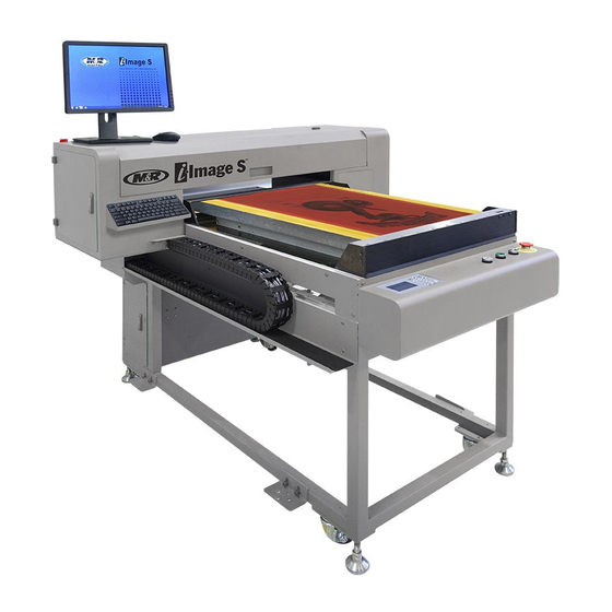
Image S programs. Any auto updates can crash the software and any unsaved data will be lost. The i-Image S is an ink jet printer designed to print a UV blocking dye directly onto the surface of a coated screen, eliminating the need for film positives. -
Page 15: Main Control Panel - I-Image S
V.120617 5.2 Main Control Panel - i-Image S Number Name Function Used to display information regarding operational, programming, and system LCD Control status messages. Panel Used to count the total number of prints. Print Counter Display Blue button used to start printing process. -
Page 16: Printer Control Panel
V.120617 5.2.1 Printer Control Panel Number Name Function LCD Display Displays operational and diagnostic text messages. Error Light Flashes (On) when error message is displayed on LCD screen. Arrow Keys Used to select settings or change parameters. Power Light Illuminates when the power is On. Used to confirm or enter menu selection. -
Page 17: Tri-Sync Bypass Switch
A service technician will turn ON the Main Power on the rear of the unit during the installation and startup. Note: Only personnel trained on the machine should operate the i-Image S. IMPORTANT: Before printing, always do a nozzle check. See Printing Nozzle Checks in the Daily/Scheduled Maintenance section of this manual. -
Page 18: Shutdown
V.120617 5.5 Shutdown Turn the Printhead valves Lever (1) up to the vertical closed position. Rotate valve levers up until they make contact to the metal stop plate. Note: Follow this procedure for Long term shutdown only. Press and hold Abort button (2) for 3-4 seconds. When the LCD screen displays Do you really want to turn off the printer? Use Arrow Left key to select Yes and then press the Enter button (3). - Page 19 V.120617 If shutting the machine down for an extended period of time, turn OFF the Main Power (5) and Power Box Disconnect Switch (6) on the side of the unit and shutdown the computer system. M&R Companies 440 Medinah Rd. Roselle, IL 60172 USA Tel: +630-858-6101 Fax: +630-858-6134 www.mrprint.com | store.mrprint.com...
-
Page 20: Printer Control Software (Pcs)
PCS Startup Double click on the PCS desktop icon to open the program. IMPORTANT: The i-Image S printer must be powered up before the PCS is opened so the software can connect and interact. The main Printer Control window displays all the current settings and print modes. The menu bar on the right side of the screen is used for Nozzle Checks and Cleaning Modes when needed. -
Page 21: Print Mode Settings
Number of Passes refers to how many passes the head must make until it prints the full width (approximately 1.25") by overlapping a portion of each previous pass. The i-Image S only runs at 12+ pass mode for 100% for the intended work processed which supports 1200 x 900 print resolution and easily supports 55 and 65 Lpi file output. -
Page 22: Print Preview Software (Pps)
V.120617 5.7 Print Preview Software (PPS) 5.7.1 Print preview Toolbar Print preview is the user interface for processing prt files generated from the art department. PPS allows the operator to confirm crucial job information and select which plates to process. Open Print Preview by double clicking on the desktop icon. -
Page 23: Importing Files Manually
V.120617 5.7.2 Importing Files Manually Print production is the main user interface for processing prt files generated from the art department. PPS allows the operator to confirm crucial job information and select which plates to process. The prt files can be imported by either clicking on the File Open icon (1) or by clicking on the File menu drop down and selecting Open prt. -
Page 24: Importing Files Automatically
Browse button (3) and navigate to the required file. It is recommended a HOT folder or QUEUE folder be set up on either a local network, or on the desktop of the i-Image S work station. If the designated folder is to reside on the desktop also select When deleting job, automatically delete prt (4). This will automatically delete the prt file when the job is finished and deleted from the print queue. -
Page 25: Display Modes
V.120617 Halftone Info (4) shown in the Print Queue is the actual lpi/dpi angle and dot shape of the outputted file. This information is helpful to the operator in selecting, based on the halftone needs, the correct mesh counts. 5.7.5 Display Modes Single and Multi View Files can be displayed in two Modes;... - Page 26 V.120617 Inverse Mode When files are imported/opened in Preview Settings they are displayed with a White background (1) as a default. In some instances it is helpful to view certain color plates with a black background. Selecting Black (2) under Background inverts the image in the preview pane to a black background with the image as white.
- Page 27 V.120617 The Zoom function works with the Single file on the Black background. This is helpful when confirming white underbase plates. The Zoom function also works in the Multiple Channel view mode. This allows the operator to confirm color plate interaction and design details if needed.
-
Page 28: Printing Files
V.120617 5.7.6 Printing Files Jobs can be printed either one color plate at a time (recommended) or multiple plates can be sent to the printer, all at the same time. To print a single file, highlight the color plate you want to print (1) and then click on the Print button (2). To print multiple files, hold down the Ctrl button on the keyboard while selecting the color plates you want to print (3) and then click on the Print button (2). -
Page 29: Art Preparation And Image Placement
6. Art Preparation and Image Placement Unlike traditional screen making where the film positives are positioned on the screen by hand, the i-Image S relies on digital information for placement. This shifts the image placement responsibilities from the screen room to the art department. - Page 30 When the file is printed on the i-Image S, the top of the art board will fall just inside of the upper edge of the Pusher Frame (Providing the image top placement is set to 0.000 in the RIP Layout Tab settings). This sets the image at 6 inches from the O.D.
- Page 31 V.120617 A typical art board template will have a center line, an i-Image top position start line and designations for right and left chest placements. Any other design elements are up to the end user. M&R Companies 440 Medinah Rd. Roselle, IL 60172 USA Tel: +630-858-6101 Fax: +630-858-6134 www.mrprint.com | store.mrprint.com...
-
Page 32: Creating And Exporting Images From Photoshop
V.120617 6.1 Creating and Exporting Images from Photoshop ColorPRINT software supports spot color channel separated Photoshop art files, but they must be exported as a Photoshop DCS 2.0 (EPS) type file. Create an image with multiple color channels in Photoshop. To save the image as a DCS 2.0 file, use the Save As menu and select the Format DCS 2.0 (EPS) (1). -
Page 33: Creating And Exporting Images From Illustrator
V.120617 6.2 Creating and Exporting Images from Illustrator ColorPRINT software supports spot color art files created in Illustrator, as well as DCS 2.0 files that have been placed in Illustrator. Many times DCS files will be incorporated into an Illustrator file in order to add registration marks and or color plate information. -
Page 34: Exporting Files From Illustrator
V.120617 DCS 2.0 Files may also be placed into Illustrator for purposes of template placement or adding color plate information and or registration marks. Refer to Art preparation and Image Placement in this manual. 6.2.1 Exporting Files from Illustrator Export finished art from Illustrator as an Illustrator EPS file. Use Save As in the Illustrator File drop down menu. -
Page 35: Colorprint Rip
V.120617 6.3 ColorPRINT RIP 6.3.1 Creating Printer Setups The ColorPRINT RIP Software allows users to set up and define a number of different Printer Profiles or Setups. Printer Setups contain all the pertinent settings that apply to the art file when it is ripped, such as halftone settings, image placement, screen size and halftone curves. - Page 36 V.120617 General Tab Once the new Printer Setup has been created right click on the icon or double click on the New Printer Setup icon to open up the Printer Setup Preferences. Under the General tab you will find the settings for automation, screen size and image placement. To automate the RIP processing, select the RIP and Print after receiving jobs (1).
- Page 37 Resolution: 1200 x 900 (1) is the most commonly used resolution and gives the best results for all types of printing. Changing resolutions may also require the i-Image S operator to select a corresponding Print Mode in the PCS software. Refer to Print Mode Settings in this manual.
- Page 38 V.120617 Adjust Tab The Adjust tab allows the setting of custom halftone curves. Testing has shown that setting the Input at 80 and the Output at 60 is a good starting point. Test to see what works best for your printing scenarios and shop conditions.
- Page 39 Get button (1) is used to access the PCS Print Modes. However in most cases the system will be configured to print to File which voids the Print Mode selection, leaving that function to the I-Image S operator.
-
Page 40: Configuring Printer Device Settings
By selecting the Multi-output port, ripped prt files can be sent to multiple locations. For example, one file is sent to a Hot Folder where it is accessed by the I-Image S operator and printed. When finished, a setting in the PPS software automatically deletes the file from the print queue. - Page 41 V.120617 The new folder path will be displayed in the Multi-output port window (3). Click on Add (2) again and search the Network for the required folder. Use Browse for Folder dialog window and the second folder path will be displayed in the Multi-output port window.
-
Page 42: Processing Art Files
V.120617 6.3.3 Processing Art Files There are a several ways to open/import art files into ColorPRINT since the RIP can be configured for multiple printer setups. It is important that the correct printer setup is highlighted when adding a job. The best way to insure this is to put the cursor on the intended Printer Setup and right click. -
Page 43: Scheduled Maintenance
V.120617 7. Scheduled Maintenance Benefits Properly maintained equipment operates more efficiently, reduces operating costs, and lasts longer. A properly managed preventive maintenance program can minimize downtime. Preparation An effective preventive maintenance program includes: proper selection, handling, and application of lubricants ... - Page 44 V.120617 As Required WARNING: To prevent possible injury to personnel and/or damage to the equipment, lock out and tag the electrical service to the equipment. Empty Waste Tank Items required: 1 - Rubber gloves 1 - Lint Free Rags 1 – Empty Container ( 2 gallons or larger) The waste tank stores ink from printhead cleaning.
-
Page 45: Fill Ink And Cleaning Solution Tanks
V.120617 Fill Ink and Cleaning Solution Tanks When the ink tank is empty, the message M-TANK LOW appears on the Printer Control Panel screen. When the cleaning tank is empty, the message F TANK LOW appears on the Printer Control Panel screen. When the tank is filled, the message is automatically eliminated. -
Page 46: Printing Nozzle Checks
V.120617 Daily WARNING: To prevent possible injury to personnel and/or damage to the equipment, lock out and tag the electrical service to the equipment. Printing Nozzle Checks Nozzle Checks should be performed on a daily basis, usually each morning or the beginning of each shift to confirm the status of the printhead. - Page 47 V.120617 Select the Check Nozzle box (2) in the right hand menu bar of the PCS Program. The screen displays Waiting for print allow. Press the Print button (3) on the control panel or Print Screen. The gantry travels to the print start position, prints one nozzle check and automatically sends the gantry to the load position.
-
Page 48: Auto Clean - Automated Head Cleanings
V.120617 Auto Clean - Automated Head Cleanings If a Nozzle Check was performed and portions were found not printing (1), run an Auto Clean. It may take two or three Auto Cleans to purge large air pockets. Select the Auto Clean box (2) in the right hand menu bar of the PCS Program. The Printer starts an automated cleaning mode which purges ink and any air out of the printhead plate. -
Page 49: General Cleaning
V.120617 Weekly WARNING: To prevent possible injury to personnel and/or damage to the equipment, lock out and tag the electrical service to the equipment. General Cleaning Wipe down all surfaces to remove dust and dirt. Inspect ink lines filters, fittings, valves, and pumps for any leaks. Check maintenance tank. - Page 50 V.120617 Open the Access Door (2) from the front left side of unit. Inspect the printhead and the printhead plate. Use a lint free rag and clean water to clean the printhead plate. IMPORTANT: Wiping directly on the printhead can cause damage from lint and from dirty or contaminated ink being wiped into the nozzle ports.
- Page 51 V.120617 With the printhead still under the left side cover open the Access Door (3) and Top Cover (4). With the printhead out of the way, use a soft cloth dampened with warm water, gently wipe and clean the vertical portions of the wiper blades (5).
- Page 52 V.120617 The Wiper Tray (7) will move back to reveal the Cap Tray (8). Keep the underline portion clean. Closely inspect the capping station (9) for any harden ink particles or chunks, carefully wipe away any debris using caution to not damage the rubber seal. Note: DO NOT USE a sharp instrument to remove debris from capping station plate as damage to the rubber seals may occur.
-
Page 53: Major Inspection And Cleaning Of Capping Station
V.120617 Monthly WARNING: To prevent possible injury to personnel and/or damage to the equipment, lock out and tag the electrical service to the equipment. Major Inspection and Cleaning of Capping Station Items required: 1 - Rubber gloves 1 - Lint Free Rags 1 - Phillips Screwdriver 1 - 3 mm Hex Head Wrench As Needed - Capping Pad (M&R Part No. - Page 54 V.120617 Using a Phillips screwdriver loosen the two bracket screws (1) holding the two wiper blades in place. Remove the individual wiper blades (2) by sliding each one out from the bracket. Thoroughly clean the parts in warm water and inspect for any damage, such as nicks, cuts or wear on the blade tips. Replace if damaged.
- Page 55 V.120617 Dry the assembly thoroughly with a soft lint free cloth and or compressed air before reinstalling it. Carefully inspect the capping tray seals (1) around the edge of the capping pad for any damage or nicks. Push down with your finger to make sure that the spring mechanism moves freely, allowing the cap to compress.
-
Page 56: Lubricate Linear Bearings
Shutdown machine as described in this manual. The Ink pump filter (1) is located in the base of the i-Image S attached to the K ink pump. Unscrew the connections on the top and bottom (2) and replace with a new filter. The filters are uni-directional. Install with the arrow (1) up. -
Page 57: Replace Printhead Filter
V.120617 Replace Printhead Filter Items required: 1 - Black Disk Filter - 20 Micron (M&R Part No. 7990090) 1 - 3/32" Hex head Wrench 1 - Rubber gloves 1 - Lint Free Rags There is secondary filter prior to the ink going into the printhead. Shutdown machine as described in this manual. - Page 58 V.120617 Yearly WARNING: To prevent possible injury to personnel and/or damage to the equipment, lock out and tag the electrical service to the equipment. Clean Ink Tank Items required: 1 - Rubber gloves 1 - Lint Free Rags Over time heavy particles will accumulate in the bottom of the tank. At about the one year mark watch the ink level.
-
Page 59: Replace Pressure Pump Filter
V.120617 Replace Pressure Pump Filter Items Required 1 - Disk Air Filter (M&R Part no. 7990007) Open the door (1) on the back left side of unit. Remove and replace one filter (2) to the Positive Pressure Pump (PP). Note: The Negative Pressure Pump does not require a filter. M&R Companies 440 Medinah Rd. -
Page 60: Scheduled Maintenance Log (Based On A 40 Hour Work Week.)
V.120617 7.1 Scheduled Maintenance Log (Based on a 40 hour work week.) Date Maintenance Procedure performed/ Initials Empty Waste Tank Fill Ink and Cleaning Solution Tanks Clean Operator Interface Display Screen Printing Nozzle Checks Auto Clean - Automated Head Cleanings General Cleaning Minor Inspection and Cleaning of Wiper Blades, Capping Station and... -
Page 61: Replacement Parts
V.120617 8. Replacement Parts CE vs. UL Models All equipment containing electrical components is designed to comply with either Conformance European (CE) or Underwriters Laboratories (UL) standards, and each type of equipment has a different parts list. CE equipment runs at 50 Hz; UL equipment runs at 60 Hz. Electrical specifications, including Hertz, can be found on the Manufacturer’s Rating Plate similar to the one shown below. - Page 62 V.120617 Boards, Power Supplies and Filters (UL & CE) Boards, Power Supplies and Filters (UL & CE) Part Numbers Part Name All Models Main Board V4.7 7990152 Black Needle Filter 7990002 X-Motion Drive and Motor 8EG0019 AC Contactor 1050010 Power supply 24V, 13A 7990029 Power supply 36V, 9.7A, 350W 7990028...
Need help?
Do you have a question about the i-Image S and is the answer not in the manual?
Questions and answers