
Related Manuals for KeLi D2002E


Summary of Contents for KeLi D2002E
- Page 1 Keli Electric Manufacturing ( Ningbo ) Co., Ltd Digital Load Cell and Indicator (D2002E) User Manual Date: January 2006 Page 1 of 38 www.kelichina.com...
-
Page 2: Table Of Contents
Contents Chapter 1 Brief Introduction 1. Basic Operating Principle of Digital Load Cell 2. Principle of Digital Indicator 3. Features and characteristics 4. Digital Load Cell and Indicator communication format Chapter 2 Technical Specification 1. Digital Load Cell Technical Guide Line 2. - Page 3 6. Weight Data Delete 7. Daily Record Print 8. Caution Chapter 11 Malfunction & Troubleshooting Chapter 12 Maintenance & Related Notice Page 3 of 38 www.kelichina.com...
-
Page 4: Chapter 1 Brief Introduction
Chapter 1 Brief Introduction 1. Basic Operating Principle of Digital Load Cell Digital Load cell system is a brand new electronic weighing appliance developed from the traditional strain gauge sensor by using modern micro-electronics technology and micro-computer integration. It includes two parts, analogue load cell (strain gauge) and digital converter module. Converter module is a high-integrated electronic circuit and adopts SMT on the surface. - Page 5 diagnosing is easy. E. High flexibility All communication via standard communication interface RS485. It is connected to PC directly or other standard industrial mastering bus. It is easy to use and build the scale. F. High security, to avoid cheat function It can prevent remote controller cheating.
-
Page 6: Chapter 2 Technical Specification
Chapter 2 Technical Specification 1. Technical specification of load cell 1. Data Conversion Rate: 10~200 measurements per second 2. Data transmission rate: 9600~38400BPS 3. Digital module A/D count: 10M counts 4. Resolution: 60000 counts 5. Digital module Zero point Temperature Coefficient: <±0.002%F.S/10℃ 6. - Page 7 Decimal point: three digits decimal point optional communication port: All photoelectricity isolation, direct connection to computer and display screen Display screen communication: RS232 & 20Ma electric current loop selectable. In case of individual connection, address number is able to be changed. 4.
-
Page 8: Chapter 3 Installation & Connection
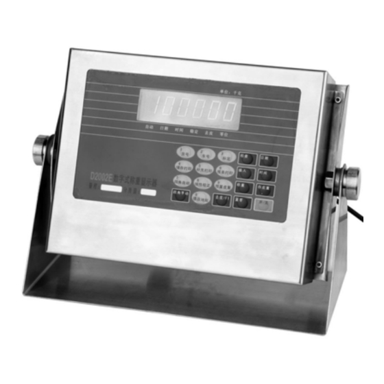
Chapter 3 Installation & Connection Front & Back view of Indicator Unit:kg AUTO DATE TIME CONST TARE ZERO DATE CARGO VEHICLE CHECK CALIBRATION Supplementary ENTER TIME MEMORY PRINT Print FORM PRINT Auto Linearity WEIGH Preset Tare Memory Tare Correction Corner-rectify Manua ZERO ON/OFF... -
Page 9: Connection Between Printer And Indicator
information To make sure the load cell and the indicator are connected effectively. The shielding conductor should be put to earth. The conductor is not allowed to be plugged in or out when the indicator is power on to avoid damage to the load cell and indicator caused by the static electricity. -
Page 10: Connection Between Display Screen And Indictor
(Chart 2-4)Printer interface signal b) Notice of Print Please set up function before operation. Make sure the indicator and printer have been connected with matched wire in a right way. Otherwise it will damage the indicator and printer terminals or equipment. - Page 11 d0 d1 d2 d3 d4 d5 d6 d7 G16 G17 (Chart 2-6.1)First frame oscillogram Second frame: d0 d1 d2 d3 d4 d5 d6 d7 G8 —————— (Chart 2-6.2)Second frame oscillogram Third frame: d0 d1 d2 d3 d4 d5 d6 d7 ——...
-
Page 12: Serial Interface
Computer skill and programmer ability are required by computer operation. Only qualified personnel are allowed to service this equipment. Load cell D2002E type realize data transmission between pc and indicator by serial interface. The transmission is continuous, baudrate 600, 1200, 2400, 9600bps are optional. - Page 13 Mode 2 X X X X X X X X X X X X CR <STX> ASCII start bit (02H). State character A,B,C Weight: it may be gross weight or net weight. 6 digits show weight without sign or decimal. Tare: 6 digits without sign or decimal <CR>...
- Page 14 Bit 0 Gross weight = 0 , net weight = 1 Bit 1 sign :plus= 0 , minus = 1 overload ( or less than 0) = 1 Bit 2 Bit 3 motion = 1 Bit 4 unit : kg = 1 keep 1 Bit 5 Bit 6...
-
Page 15: Chapter 4 Look Over Ins (Internal Statement Number) Of Load Cell
Chapter 4 Look over INS (internal statement number) of load cell Please plug calibration plug into 15 pins RS232 at the back of indicator for load cell INS information. The ISN provides technical parameters for manual Corner adjustment and information for us to judge it is malfunction or not. Please refer to the below chart for detailed information.( * is original value, load cell number starts 01, if 4 load cells in total they are 01,02,03,04) Step... -
Page 16: Chapter 5 Corner Adjustment
Chapter 5 Corner adjustment 1. Manual Corner adjustment Please plug calibration plug into 15 pins RS232 at the back of indicator for manual Corner adjustment. Please refer to the below chart for detailed information. (* original value, load cell number starts 01, if there are 4 load cells in total, they are 01,02,03,04 ) Step Operation Display... - Page 17 Steps Operation Display Note Press[Auto [-------] Note to enter password Corner-Rectify] Enter Only if the password is 111111 can you 1.Power on and [1][1][1][1][1][1] [111111] choose carry on the next step, otherwise return to , operating mode the weighing states. Press[Enter] [Ant 04] Default load cells number is 4;...
-
Page 18: Chapter 6 Calibration
Chapter 6: Calibration When indicator is packed before leaving factory, there is also a 15 pins RS232 plug, called calibration plug which is used to set the related coefficient between the indicator and load cells. When the indicator is working, the calibration plug should not be plugged in. Any time when the plug used, following process should be adopted. - Page 19 Steps Operation Display Note The Calibration plug has been plugged in Press under weighing state. [Calibration] [d1 **] Means setting the first part division value; Set the first part division value to 05, 01~99 Press[0][5] [d1 05] available. Press [Check] to skip this step, press [Weight] back to the weighing state 1.Set division Press[Enter]...
- Page 20 [Prt **] Display original set ponderation form printing Press[0][1] format [Prt 01] Set printing format to 1, that is non printing single unite format 4.Set Choices: 00、 01、 02、 03 series, they are filling ponderation Press[Enter] style, non filling single unite, non filling double form printing unite, non filling three or four unite.
- Page 21 [Pont **] Display original set decimal number Press[0][1] [Pont 01] Set the decimal number to one. 00、01、02、03 is available. They are separately no decimal, 7.Set displayed one decimal, two decimal and three decimal. decimal Press[Enter] Press [Check] to skip this step, press [Weight] number back to the weighing state Press [Enter] to finish the setting of displayed...
- Page 22 weave is. Press [Check] to skip this step, press [Weight] back to the weighing state Press [Enter] finishes the setting of strain Press[Enter] wave coefficient. [SC **] Display original set units code; 11.Set Press [0]、[1] [SC 01] Set units code to 01, 00,01,02 is available, ponderation 00 stands for kg、01 stands for T(ton)、02 form...
- Page 23 [noLoAd] Check scale dead load span. Press [Enter] [Enter] after the scale is unloaded and stable Displays the ISN value under unload state, [000000] which should close to zero. Check [Enter] Press [Check] to skip this step, press [Weight] scale dead load [------] back to the weighing state span...
-
Page 24: Chapter 7 Adjust The Address Of Load Cell
Chapter 7: Adjust the address of Load Cell If address needs to be changed, the indicator should turn off first. Connect the load cell ( : needed to change address and disconnect others. Note the indicator can only connect one load cell. )... -
Page 25: Chapter 8 Setting Of Scale's Linearity Adjustment
Chapter 8 Setting of Scale’s Linearity Adjustment 1. Operation Method: ▲!Before this operation, the calibration plug should plug in the 15 pin RS232 jack in the back of the indicator. Before revising, load the weight which needs to be revised (For example: a scale fits to the linearity requirements on weight 0-30T but not on 40T, then the scale’s revising load point should be 40T)... -
Page 26: Chapter 9 Installation & Debugging
Chapter 9 Installation & Debugging 1. Installation of Scale platform & Load Cell Install the platform and load cells on the Foundation level that previously prepared. During installation, ensure the precision of the load cells’ location and let the platform fully press on the load cells. -
Page 27: Four Corner Adjustment
of the platform share a greater weight. This proportion is about 2:1. In order that the platform shares a uniform force, we require the ISN max. Value minus min. value of the four load cells on margin less than 400; Likely the max. ISN value minus min. ISN value of the four load cells in center less than 400.(If the scale has 8 load cells, then there are 4 load cells in the center). -
Page 28: Calibration
Estimated Formula is as follows: Difference Corner-Rectify Coefficient K=1- ———————— =1- —————— Pressing Weight *75% 10000*75% You can also directly try several data to avoid estimation. Note: If the weight is 10kg less, then the difference in the formula will be –10. Auto Corner -Rectify: For details refer to Chapter 5. -
Page 29: Chapter 10 Operation
Chapter 10: Operation 1. Start-up & Automatic-zero setting at start-up Power on. The indicator will be under measuring status after self examination from ‘000000’ to ‘999999’. After start-up, the device will compensate for small changes in zero if the value is not zero but still in the zero range (±4% ±10% ±20% ±40% ±100%F.S are optional) ‘Deduct Tare’... - Page 30 Vehicle number must be a value between 00001 and 99999. That is to say 0000 is not a legal vehicle number. If the number is 00000, the third method is adopted to weigh the goods. If the tare is known already, one time testing is enough to have the full record.
- Page 31 STEP two: Step Description Display Notes Under measuring Input Vehicle No.:12345 status Press [Err 44] is displayed if the vehicle [Memory Print] Input vehicle NO. [o12345] NO. does not exist, press [Enter] press[Enter] back to measuring status Input [3][5] [hn 35] Cargo NO.:35 press[Enter] Back to measuring status...
- Page 32 Chapter 11: Malfunction & Troubleshooting 1. Malfunction description: No display and no buzz after power on. Possible Reason: Maybe the fuse is broken, or no power source, or the transformer inside crashes because of high voltage. Solution: Change a new fuse, check the electricity, or check the transformer. 2.
- Page 33 Turn the indicator off, plug in the address modifying plug, and connect the sensor to the indicator (they can only be tested one by one). Power on, the code of the sensor will be displayed after self examination. Press ENTER, the load value will be shown according which we can indicate whether the sensor is ok or not (find detailed information in section 7).
- Page 34 14. Malfunction description: It gives a big number after booting, and it jumps in a wide range. Possible reason: unstable voltage or environmental interfere Solution: strengthen the stability of electricity and earth the device. Test the voltage of the metal cover if it has, earth the cover if necessary. 15.
- Page 35 7. Never put water or other mess into the device. 8. Weighing screen is a precise measuring tool, inside installation and debugging must be operated with the permission of national measuring department or Keli Electric Manufacturing CO., Ltd, others have no right to make the amendment.
- Page 36 Appendix: 1. Weight bill ( full printed): 一联: 过磅单 first page WEIGHT BILL 序号 SERIAL 0001 日期 DATE 02-08-21 时间 TIME 17:33:09 车号 VEHICLE 012345 货号 CARGO 毛重 GROSS 9905kg 皮重 TARE 500kg 净重 NET 9405kg 司磅员/operator: 二联: 过磅单 过磅单 Second page WEIGHT BILL...
- Page 37 司磅员/operator: 司磅员/operator: 三联:third page 过磅单 过磅单 过磅单 WEIGHT BILL WEIGHT BILL WEIGHT BILL 序号 SERIAL 0001 序号 SERIAL 0001 序号 SERIAL 0001 日期 DATE 02-08-21 日期 DATE 02-08-21 日期 DATE 02-08-21 时间 TIME 17:33:09 时间 TIME 17:33:09 时间 TIME 17:33:09 车号...
- Page 38 日报表/daily report form 日期/date:02-08-23 序号 时间 车号 毛重 皮重 净重 货号 cargo serial time vehicle Tare 0001 11:31:37 011111 3998Kg 500Kg 3498Kg 0002 11:32:11 012345 3997Kg 500Kg 3497Kg 0003 11:37:05 099999 3997Kg 850Kg 3147Kg 0004 14:26:25 000000 3999Kg 3999Kg Page 38 of 38 www.kelichina.com...
Need help?
Do you have a question about the D2002E and is the answer not in the manual?
Questions and answers