
Related Manuals for SeaLevel COMM+8


Summary of Contents for SeaLevel COMM+8
- Page 1 COMM+8 ™ User Manual | 3420 © Sealevel Systems, Inc. 3420 Manual | SL9145 9/2022...
-
Page 2: Table Of Contents
APPENDIX C – ELECTRICAL INTERFACE ......................19 APPENDIX D – ASYNCHRONOUS COMMUNICATIONS .................. 20 APPENDIX E – SILK SCREEN ..........................21 APPENDIX F – COMPLIANCE NOTICES ......................22 WARRANTY ................................ 23 © Sealevel Systems, Inc. 3420 Manual | SL9145 9/2022... -
Page 3: Introduction
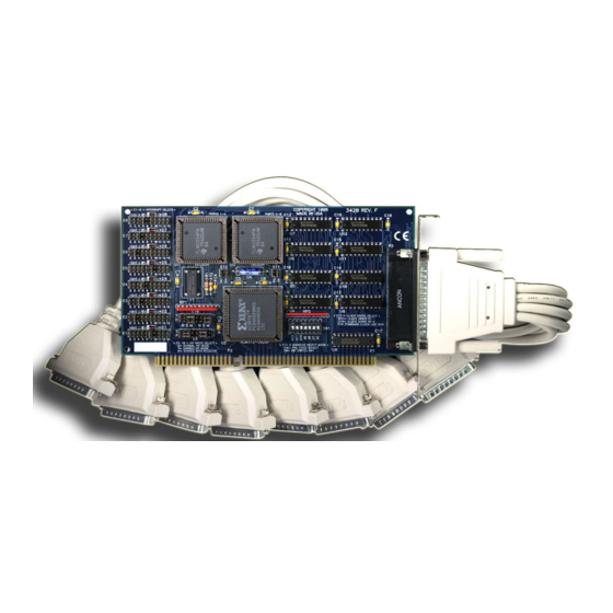
Introduction Overview The Sealevel Systems COMM+8 provides the PC with eight RS-232 asynchronous ports. The COMM+8 allows for connection to any device utilizing the RS-232 electrical interface, such as modems, data-entry terminals, and plotters. © Sealevel Systems, Inc. 3420 Manual | SL9145... -
Page 4: Before You Get Started
Before You Get Started What’s Included The COMM+8 is shipped with the following items. If any of these items is missing or damaged, contact the supplier. COMM+8 Serial I/O Adapter • • “Octopus” Cable providing 8 DB-25 or DB-9 connectors... - Page 5 Port 4 Port 5 Port 6 Port 7 Port 8 To install the COMM+8 using factory default settings, refer to the Installation section of this manual. For your reference, record installed COMM+8 settings below: Port # Base Address Port 1...
- Page 6 The following table illustrates the port assignments for the Factory Default setting. Port # DB-25# Address Example Base+0 280-287 Base+8 288-28F Base+16 290-297 Base+24 298-29F Base+32 2A0-2A7 Base+40 2A8-2AF Base+48 2B0-2B7 Base+56 2B8-2BF © Sealevel Systems, Inc. 3420 Manual | SL9145 9/2022...
-
Page 7: Card Setup
The COMM+8 contains several jumper straps that must be set for proper operation. Address Selection The COMM+8 occupies 64 I/O locations and can be addressed two different ways. If header E11 is set to the “Switch” position the COMM+8 occupies 64 consecutive I/O locations, and the DIP-switch is used to set the base address for these locations. - Page 8 IRQ Selection Each port on the COMM+8 has an interrupt jumper that may have to be set prior to use. The software you are using with the board will determine which interrupts, if any are to be used. The DOS serial port interface software does not use interrupts, while interrupt buffer programs do.
- Page 9 Figure 5 - Header E9 and E10, Shared IRQ Mode Set all jumpers to “S” if you are using more than one COMM+8 in a bus or you wish to completely remove the pull-down resistor for hardware compatibility. Setting the COMM+8 in this configuration when it is not accompanied by a pull-down resistor will prevent the ports from triggering an interrupt.
- Page 10 Clock Modes The COMM+8 employs a unique clocking option that allows the user to select from divide by 4 or divide by 1 clocking modes. This mode is selected at E12. To select the Baud rates commonly associated with COM: ports (i.e., 2400, 4800, 9600, 19.2, … 115.2K Bps) place the jumper in the divide by 4 mode (silk-screen DIV4).
-
Page 11: Installation
Only users running Windows 7 or newer should utilize these instructions for accessing and installing the appropriate driver via Sealevel’s website. If you are utilizing an operating system prior to Windows 7, please contact Sealevel by calling 864.843.4343 or emailing support@sealevel.com... - Page 12 The COMM+8 can be installed in any 16-bit PC expansion slot. The COMM+8 contains several jumper straps for each port that must be set for proper operation prior to installing the COMM+8 into the computer. 1. Turn off PC power. Disconnect the power cord.
-
Page 13: Technical Description
All eight status ports on the COMM+8 are identical, so any one of the eight can be read. If header E11 is in the “PAL” position, the status port can be addressed at any location. - Page 14 Request To Send Output Data Terminal Ready Output Receive Data Input Clear To Send Input Data Set Ready Input Data Carrier Detect Input Ring Indicator Input Figure 10 - DB-9 Connector Pin Assignments © Sealevel Systems, Inc. 3420 Manual | SL9145 9/2022...
- Page 15 RTS to CTS and RI. Also, connect DCD to DTR and DSR. Terminating these pins, if not used, will help insure you get the best performance from your adapter. © Sealevel Systems, Inc. 3420 Manual | SL9145...
-
Page 16: Specifications
Mean Time Between Failures (MTBF) Greater than 150,000 hours. (Calculated) Physical Dimensions Board length 7.0 inches (17.78 cm) Board height including Goldfingers 4.2 inches (10.66 cm) Board height excluding Goldfingers 3.9 inches (9.91 cm) © Sealevel Systems, Inc. 3420 Manual | SL9145 9/2022... -
Page 17: Appendix A - Troubleshooting
No two adapters can occupy the same I/O address. Make sure the Sealevel Systems adapter is using a unique IRQ The IRQ is typically selected via an on-board header block. Refer to the section on Card Setup for help in choosing an I/O address and IRQ. -
Page 18: Appendix B - How To Get Assistance
If possible, please have the adapter installed in a computer ready to run diagnostics. 3. Sealevel Systems provides an FAQ section on its web site. Please refer to this to answer many common questions. This section can be found at http://www.sealevel.com/faq.asp. -
Page 19: Appendix C - Electrical Interface
0 (space) and -12 volts (-3 to -10 volts) denotes a binary 1 (mark). The RS-232 and the EIA/TIA-574 specification define two types of interface circuits Data Terminal Equipment (DTE) and Data Circuit-Terminating Equipment (DCE). The Sealevel Systems Adapter is a DTE interface. © Sealevel Systems, Inc. -
Page 20: Appendix D - Asynchronous Communications
The communication parameters are baud rate, parity, number of data bits per character, and stop bits (i.e.,9600,N,8,1). © Sealevel Systems, Inc. 3420 Manual | SL9145 9/2022... -
Page 21: Appendix E - Silk Screen
Appendix E – Silk Screen 3.9" 7.0" 4.2" © Sealevel Systems, Inc. 3420 Manual | SL9145 9/2022... -
Page 22: Appendix F - Compliance Notices
Always use cabling provided with this product if possible. If no cable is provided or if an alternate cable is required, use high quality shielded cabling to maintain compliance with FCC/EMC directives. © Sealevel Systems, Inc. 3420 Manual | SL9145... -
Page 23: Warranty
Sealevel's commitment to providing the best I/O solutions is reflected in the Lifetime Warranty that is standard on all Sealevel manufactured I/O products. We are able to offer this warranty due to our control of manufacturing quality and the historically high reliability of our products in the field. Sealevel products are designed and manufactured at its Liberty, South Carolina facility, allowing direct control over product development, production, burn-in and testing.
Need help?
Do you have a question about the COMM+8 and is the answer not in the manual?
Questions and answers