
Related Manuals for SeaLevel DIO-104.OPTO


Summary of Contents for SeaLevel DIO-104.OPTO
- Page 1 DIO-104.OPTO User Manual | 3720 © Sealevel Systems, Inc. 3720 Manual | SL9019 7/2021...
-
Page 2: Table Of Contents
INTRODUCTION ..............................3 BEFORE YOU GET STARTED ..........................4 CARD SETUP ................................ 6 SOFTWARE INSTALLATION ..........................7 PHYSICAL INSTALLATION ..........................10 PROGRAMMING THE DIO-104.OPTO ....................... 11 ELECTRICAL CHARACTERISTICS ........................14 SPECIFICATIONS ............................... 15 EXAMPLE CIRCUITS ............................16 APPENDIX A – TROUBLESHOOTING........................ 17 APPENDIX B –... -
Page 3: Introduction
Introduction The DIO-104.OPTO is a PC/104 form factor adapter that provides 16 optically isolated inputs (rated for 3- 13V) to allow monitoring of off board switch closures, relays or for any other general purpose monitoring needs. The DIO-104.OPTO is designed to be used with a variety of Operating Systems including Windows and DOS. -
Page 4: Before You Get Started
Before You Get Started Wat’s Included The DIO-104.REL is shipped with the following items. If any of these items are missing or damaged, please contact Sealevel for replacement. • DIO-104.OPTO Adapter Advisory Conventions Warning The highest level of importance used to stress a condition where damage could result to the product, or the user could suffer serious injury. - Page 5 DIO-104.OPTO and provides a DB-37 Female connector. DB-37 Male to DB-37 Female 6’ Cable - (Part Number CA112) This cable extends the DB-37 connector on the DIO-104.OPTO to six feet and is pinned one-to-one. DB-37 Male/Female Terminal Block (Part Number TB02-KT) Break out serial and digital connectors to 37 screw terminals for easy field connection.
-
Page 6: Card Setup
Card Setup Address Selection The DIO-104.OPTO occupies 4 consecutive I/O locations. The DIP-switch (S1) is used to set the base address for these locations. Be careful when selecting the base address as some selections conflict with existing PC ports. The following table shows several examples that usually do not cause a conflict. Even though four I/O addresses are decoded, only the first two are actually used, the other two ports are to maintain compatibility with existing Sealevel Systems adapters. -
Page 7: Software Installation
Only users running Windows 7 or newer should utilize these instructions for accessing and installing the appropriate driver via Sealevel’s website. If you are utilizing an operating system prior to Windows 7, please contact Sealevel by calling 864.843.4343 or emailing support@sealevel.com... - Page 8 8. User must download and compile a Linux kernel source. 9. Now compile and prepare the drivers for use by typing: make install 10. Using your favorite text editor, edit the /etc/seaio.conf 11. Within the quote marks, insert cardtype=0xYourSeaIOcardType io=0xCardBaseAddress © Sealevel Systems, Inc. 3720 Manual | SL9019 7/2021...
- Page 9 To set up Linux to automatically load the driver; refer to a Linux manual concerning your specific distribution for help. For additional software support, please call Sealevel Systems’ Technical Support, (864) 843-4343. Our technical support is free and available from 8:00 AM - 5:00 PM Eastern Time, Monday through Friday. For email support contact: support@sealevel.com.
-
Page 10: Physical Installation
Physical Installation Extreme care should be taken when installing the DIO-104.OPTO to avoid causing damage to the connectors. After the adapter is installed, connect your I/O cable to P2. Please note these headers are keyed so that pin 1 of the cable matches pin 1 of the connector. Refer to Card Setup for information on setting the address before inserting the DIO-104.OPTO onto the stack. -
Page 11: Programming The Dio-104.Opto
Digital I/O Interface The DIO-104.OPTO provides four parallel input/output (I/O) ports. The ports are organized as ports A, B, C, and D. Ports A and B are input ports interfaced to optically-isolated inputs, while ports C and D decoded but not used. - Page 12 16.9V 15mA 2.2KW 7.7V 7.7 – 20.0V 24.5V 10mA 3.3KW 10.0V 10.0 – 24.0V 30.0V 4.7KW 15.2V 15.2 – 28.0V 35.0V The turn-off voltage for all resistors is less than 1V. © Sealevel Systems, Inc. 3710 Manual | SL9128 7/2021...
- Page 13 Increasing the input resistor accordingly can increase the maximum input voltage. Because socketed DIP resistors are utilized, they can easily be replaced with a different value. Sealevel, if necessary can do this. The input circuits are not intended for monitoring 120-volt AC circuits. In addition to being too high a voltage for the circuits, it is dangerous to have that high a voltage on the card.
-
Page 14: Electrical Characteristics
2 eight bit input ports • Selectable I/O port addressing from 100H - 3FFH • Multiple adapters can reside in same computer • All address, data and control signals are TTL compatible © Sealevel Systems, Inc. 3710 Manual | SL9128 7/2021... -
Page 15: Specifications
3.8” (9.6 cm) Manufacturing All Sealevel Systems Printed Circuit boards are built to UL 94V0 rating and are 100% electrically tested. These printed circuit boards are solder mask over bare copper or solder mask over tin nickel. © Sealevel Systems, Inc. -
Page 16: Example Circuits
Example Circuits Input Circuit © Sealevel Systems, Inc. 3710 Manual | SL9128 7/2021... -
Page 17: Appendix A - Troubleshooting
• 2E8-2EF is typically reserved for COM4: If these steps do not solve your problem, please call Sealevel Systems’ Technical Support, (864) 843-4343. Our technical support is free and available from 8:00 A.M.to 5:00 P.M. Eastern Time Monday through Friday. -
Page 18: Appendix B - How To Get Assistance
If possible, please have the adapter installed in a computer ready to run diagnostics. 3. Sealevel Systems provides an FAQ section on its web site. Please refer to this to answer many common questions. This section can be found at http://www.sealevel.com/faq.htm... -
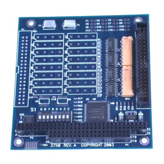
Page 19: Appendix C - Silk Screen - 3720 Pcb
Appendix C – Silk Screen – 3720 PCB © Sealevel Systems, Inc. 3710 Manual | SL9128 7/2021... -
Page 20: Appendix D - Compliance Notices
Always use cabling provided with this product if possible. If no cable is provided or if an alternate cable is required, use high quality shielded cabling to maintain compliance with FCC/EMC directives. © Sealevel Systems, Inc. 3710 Manual | SL9128 7/2021... -
Page 21: Warranty
Sealevel's commitment to providing the best I/O solutions is reflected in the Lifetime Warranty that is standard on all Sealevel manufactured I/O products. We are able to offer this warranty due to our control of manufacturing quality and the historically high reliability of our products in the field. Sealevel products are designed and manufactured at its Liberty, South Carolina facility, allowing direct control over product development, production, burn-in and testing.
Need help?
Do you have a question about the DIO-104.OPTO and is the answer not in the manual?
Questions and answers