Table of Contents
Advertisement
Advertisement
Table of Contents
Troubleshooting

Related Manuals for EXFO LTB Series


Summary of Contents for EXFO LTB Series
- Page 1 User Guide LTB Series www.EXFO.com...
- Page 2 EXFO Inc. (EXFO). Information provided by EXFO is believed to be accurate and reliable. However, no responsibility is assumed by EXFO for its use nor for any infringements of patents or other rights of third parties that may result from its use.
-
Page 3: Table Of Contents
Contents Contents Regulatory Information ......................vii 1 Introducing the LTB Series Unit ..............1 Main Features .........................1 LTB-2 ............................3 LTB-8 ............................5 LTB-12 ............................7 LED Indicators Description ......................9 Function Buttons Description ....................12 Product Registration ......................13 Technical Specifications ......................13 Conventions ..........................14 2 Safety Information ..................15 Other Safety Symbols on Your Unit ..................17... - Page 4 Freeing Up Disk Space with the Disk Cleanup Utility ............145 Connecting to a VPN from Your Unit ..................149 9 Accessing Your Unit Remotely ..............155 Working with Remote Desktop ...................157 Working With VNC ......................167 Adding Exceptions to the Firewall ..................174 LTB Series...
- Page 5 Accessing the Online Documentation .................297 Contacting the Technical Support Group ................298 Viewing System Information ....................299 Transportation ........................303 14 Warranty ....................305 General Information ......................305 Liability ..........................306 Exclusions ...........................306 Certification ........................306 Service and Repairs ......................307 EXFO Service Centers Worldwide ..................308 LTB Series...
- Page 6 D COM Properties and Events ..............391 ActiveX (COM/DCOM)—Quick Reference ................392 Properties ...........................393 Events ..........................400 E Communicating Through TCP/IP Over Telnet ..........401 Executing SCPI Commands Over Telnet ................401 Accessing Modules ......................407 Internal Commands of the TCP/IP over Telnet Protocol ............409 Index .......................421 LTB Series...
-
Page 7: Regulatory Information
Electronic test and measurement equipment is exempt from FCC part 15, subpart B compliance in the United States of America and from ICES-003 compliance in Canada. However, EXFO Inc. makes reasonable efforts to ensure compliance to the applicable standards. The limits set by these standards are designed to provide reasonable protection against harmful interference when the equipment is operated in a commercial environment. -
Page 9: Introducing The Ltb Series Unit
Introducing the LTB Series Unit Main Features Your unit includes the following: Two, eight, or twelve module slots, depending on the model Two separated network controllers (one can be used for extended remote management with Intel Active Management Technology –... - Page 10 Note: In many procedures, the illustrations show the LTB-8 unit. However, unless otherwise specified, the information applies to all models of the LTB Series. LTB Series...
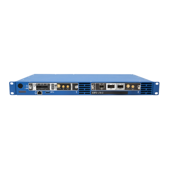
- Page 11 Introducing the LTB Series Unit LTB-2 LTB-2 Front panel On/Off button LEDs Module slots USB 3.0 host port Ethernet (RJ-45) management port for local access (to connect a portable computer to the unit) Built-in display (for network/system information) LTB Series...
- Page 12 Introducing the LTB Series Unit LTB-2 Back panel Dry contact relays (reserved for future use) DC power inlet (dual feed) Main power switch Grounding lug USB 3.0 host ports Ethernet (RJ-45) management port Ethernet (RJ-45) port (for local access) (for LAN/WAN connection) Note: You can also connect the unit to AC power with the AC/DC power adapter sold by EXFO.
- Page 13 Introducing the LTB Series Unit LTB-8 LTB-8 Front panel On/off button LEDs Built-in display (for network/system information) Ethernet (RJ-45) management port for local access (to connect a portable computer to the unit) USB 3.0 host ports Module slots Module eject button...
- Page 14 Introducing the LTB Series Unit LTB-8 Back panel Ethernet (RJ-45) management port Trigger and (for local access) synchronization ports (reserved for future Ethernet (RJ-45) port use. See Locating the (for LAN/WAN connection) Synchronization Ports (LTB-8 Only) on Replaceable hard drives...
- Page 15 Introducing the LTB Series Unit LTB-12 LTB-12 Front panel On/off button USB 3.0 host ports Built-in display (for network/system information) with activation button LEDs Module slots Module eject button (one per module slot) Module LEDs LTB Series...
- Page 16 Introducing the LTB Series Unit LTB-12 Back panel Ethernet (RJ-45) port (for LAN/WAN connection) Ethernet (RJ-45) management port (for local access) USB 3.0 host ports Grounding lug Main power switch Replaceable hard drives AC socket External monitor port (for any monitor compatible with a VGA interface) External monitor port (for any monitor compatible with HDMI) Audio ports (one for a headset or speaker and one for a microphone, all having 3.5 mm...
-
Page 17: Led Indicators Description
Introducing the LTB Series Unit LED Indicators Description LED Indicators Description There are several LED indicators located on the front panel of your unit, providing you with information about the power, system, and module statuses (module LEDs available on LTB-8 and LTB-12 only). - Page 18 Introducing the LTB Series Unit LED Indicators Description Status Meaning Reading or writing operations are currently performed on the hard disk. Hard disk Unit is off, or no reading or writing operations are currently performed on the hard disk. H/S – Hot Swap...
- Page 19 Introducing the LTB Series Unit LED Indicators Description Status Meaning ERROR The detected temperature of the (one LED per corresponding module is too high. This module slot) could lead to a thermal shutdown of the module if no action is taken to reduce the temperature.
-
Page 20: Function Buttons Description
Introducing the LTB Series Unit Function Buttons Description Function Buttons Description Your unit is equipped with function buttons that give you access to features at all times. The table below shows an overview of their purpose. Button Meaning Turns your unit on and off. -
Page 21: Product Registration
Product Registration Product Registration You can now register your new EXFO products either online or directly from your unit (if it is connected to the Internet), and benefit from every possible opportunity to optimize their performance. By doing so, you will... -
Page 22: Conventions
Introducing the LTB Series Unit Conventions Conventions Before using the product described in this guide, you should understand the following conventions: ARNING Indicates a potentially hazardous situation which, if not avoided, could result in death or serious injury. Do not proceed unless you understand and meet the required conditions. -
Page 23: Safety Information
ARNING Use only accessories designed for your unit and approved by EXFO. For a complete list of accessories available for your unit, refer to its technical specifications or contact EXFO. - Page 24 Safety Information MPORTANT Refer to the documentation provided by the manufacturers of any accessories used with your EXFO product. It may contain environmental and/or operating conditions limiting their use. MPORTANT When you see the following symbol on your unit , make sure that you refer to the instructions provided in your user documentation.
-
Page 25: Other Safety Symbols On Your Unit
Direct current Alternating current The unit is equipped with an earth (ground) terminal. The unit is equipped with a protective conductor terminal. The unit is equipped with a frame or chassis terminal. On (Power) Off (Power) On/off (Power) Fuse LTB Series... -
Page 26: Laser Safety Information
Refer to the user documentation of the different modules for the relevant laser safety information. The modules and instruments that you use with your unit may have different laser classes. Refer to their user documentation for the exact information. LTB Series... - Page 27 Refer to the user documentation of the different modules for the relevant laser safety information. The modules and instruments that you use with your unit may have different laser classes. Refer to their user documentation for the exact information. LTB Series...
-
Page 28: Electrical Safety Information
Safety Information Electrical Safety Information Electrical Safety Information The information presented hereafter applies to all LTB Series units, unless otherwise specified. ARNING LTB-2: A readily accessible disconnect device must be installed on the mains (AC or DC circuits). The power cord of the AC/DC power adapter can be considered the disconnect device to the main power. - Page 29 Unless otherwise specified, all interfaces are intended for connection to ES1 circuits only. Capacitors inside the unit may be charged even if the unit has been disconnected from its electrical supply. AUTION Position the unit so that the air can circulate freely around it. LTB Series...
- Page 30 ; 50/60 Hz; 5 - 2.5 A Measured in 0 °C to 31 °C (32 °F to 87.8 °F) range, decreasing linearly to 50 % at 40 °C (104 °F). Not exceeding ± 10 % of the nominal voltage. Range: –38.5 - –70 V LTB Series...
- Page 31 The operation and storage temperatures, as well as the altitude and relative humidity values of some modules may differ from those specified for your unit. In this case, always ensure that you comply with the most restrictive conditions (either module or unit). LTB Series...
-
Page 32: Automatic Fan Speed Management
If the temperature keeps rising and reaches the limit, your unit will turn off. This safety feature protects the unit and its modules against overheating. AUTION Make sure to use protective covers over empty slots of your unit to avoid overheating. LTB Series... -
Page 33: Getting Started With Your Unit
To avoid serious injury or irreparable damage to your units, NEVER STACK MORE THAN FOUR (4) UNITS on top of each other. Maximum of four units (LTB-8 units shown) LTB Series... - Page 34 (maximum of four units), always ensure that they are stable and that they cannot fall causing injuries or damage. DO NOT stack a mix of LTB-2 units and other type of LTB Series units. For your safety and to avoid damaging the units, regardless of the model of your units, always ensure that the bumpers (or feet) are affixed to your units before stacking them.
- Page 35 Using Your Unit as a Benchtop Unit To install the rubber feet on your LTB-2 unit: 1. Position the unit so that its top panel rests on a flat surface such as a table. 2. Attach the four feet with the provided screws. LTB Series...
- Page 36 (peel the protector sheet at the back of the foam pieces). 2. Attach the eight bumpers to the unit using the provided screws (the four bumpers with foam pieces go on the bottom panel). Bumpers with foam pieces LTB Series...
-
Page 37: Installing Your Unit In A Rack
Getting Started with Your Unit Installing Your Unit in a Rack Installing Your Unit in a Rack The table below gives you the installation requirements for your specific model of LTB Series. Minimum Minimum vertical Supported clearance for Minimum clearance... - Page 38 Failure to provide adequate cooling clearance may result in an excessive internal temperature, thus reducing the reliability of your unit. Note: There is no need to leave an empty slot between units when you stack them one on top of the other inside a rack. LTB Series...
- Page 39 The fully-configured unit is heavy. Use caution when manipulating the unit. A lifting mechanism may be required for installation. MPORTANT To let the front USB and management ports free for potential maintenance, EXFO recommends to keep all non-optical connections to the back of the unit. LTB Series...
- Page 40 4. Align the holes of the first bracket with the holes of the unit’s casing at the position that best suits your installation needs. You can even invert position of the mounting bracket if necessary. Brackets in standard position LTB Series...
- Page 41 To ground your unit properly, you must ensure that there is a metal-to-metal contact between the rack and the mounting hardware. For this reason, EXFO recommends to use thread-forming screws, star (tooth) lock washers, or similar hardware that remove any paint or non-conductive coatings.
- Page 42 2. Remove the bumpers of your unit by unscrewing the top and bottom screws. AUTION You should remove all your modules before installing your unit into a rack. Otherwise, they could be damaged or their calibration could be affected. LTB Series...
- Page 43 Ensure that the mounting panel is flush with the front panel of the unit. Front Mounting panel Air intake Left panel Screw holes Screw holes LTB Series...
- Page 44 5. Repeat steps 3 and 4 with the other mounting panel. 6. Place the unit in the rack at the desired height. 7. Fix the unit in place using the hardware supplied with the rack (two screws per side). LTB Series...
-
Page 45: Grounding Your Unit
This cable serves as a ground when connected to an appropriate AC power outlet. Depending on your setup, you may also want to ground your unit with the grounding lug that serves as a frame (chassis) terminal. LTB Series... - Page 46 Getting Started with Your Unit Grounding Your Unit To ground your unit: 1. Remove the two Phillips screws and the grounding lug from the back panel of your unit. LTB-2 LTB-8 LTB Series...
- Page 47 3. Use the two Phillips screws to attach the grounding lug and wire assembly to the back panel of your unit. 4. Ground the other end of the wire as per your local regulation. Your unit is now grounded properly. LTB Series...
-
Page 48: Connecting A Monitoring Device To The Dry Contact Relays (Ltb-2 And Ltb-8 Only)
Note: On the LTB-2, the application relay is reserved for future use. AUTION For optimum performance and safety, you must either crimp a terminal (ferrule) onto the stranded conductors, or tin them before installing them in the terminal block. LTB Series... - Page 49 2. When the terminal block is loose, gently pull it toward you to remove it, exposing the pins. 3. Crimp each wire with a terminal (ferrule) or tin each of them. 4. Unscrew the screws (shown in grey) located at the top of the terminal block. LTB Series...
- Page 50 Pin 8 - C = Common Pin 3 - NC = Normally closed Pin 9 - NC = Normally closed System relay Pin 4 - NO = Normally open Pin 5 - C = Common Pin 6 - NC = Normally closed LTB Series...
- Page 51 Pin 3 - NC = Normally Closed Pin 2 - C = Common Pin 1 - NO = Normally Open 6. Tighten the screws located at the top of the terminal block to secure the wires in place. LTB Series...
- Page 52 7. Ensure that the terminal block is aligned properly with the bay containing the pins. 8. Slide the terminal block all the way into the bay until it stops. 9. Screw the two screws to secure the terminal block in place. The dry contact relays are now installed properly. LTB Series...
-
Page 53: Locating The Synchronization Ports (Ltb-8 Only)
The synchronization and trigger ports are not currently supported by your unit. They are reserved for future use only. Back BNC synchronization port Trigger input port PPS and ToD synchronization port Trigger output port External clock synchronization port LTB Series... -
Page 54: Inserting And Removing Test Modules
To avoid damaging your unit, use it only with modules approved by EXFO. To insert a module into the unit: 1. If you work with an LTB-2 or an LTB-8 unit: Take the module and place it horizontally so that the connector pins are at the back, and the protruding edges are facing downwards. - Page 55 Protruding edges Identification sticker 2. Insert the protruding edges of the module into the grooves of the receptacle’s module slot. 3. Push the module all the way to the back of the slot, until it stops. LTB Series...
- Page 56 “seated” position. The faceplate of the module should be flush with the front panel of the unit. LTB-8 shown Turn retaining screw clockwise The module is detected automatically after the insertion (no need to restart the unit). LTB Series...
- Page 57 ToolBox X. If you are working with an LTB-8 or an LTB-12 unit, you can also wait until the H/S LED turns steady blue on its front panel. 2. Turn the two retaining screws counterclockwise until they are loose (do not remove them completely). LTB-8 shown Turn retaining screw counterclockwise LTB Series...
- Page 58 Always pull out a module by its casing or the retaining screws. 4. Cover empty slots with the supplied protective covers. AUTION Failure to reinstall protective covers over empty slots will result in ventilation problems. LTB Series...
-
Page 59: Connecting Your Ltb-2 Unit To A Power Source
To avoid damaging your unit, always ensure that the unit’s main power switch (located on the back panel) is in the off position before connecting the unit to DC or AC power. LTB Series... - Page 60 Note: A certified over-current protection of 10 A must be installed at the power secondary distribution. 3. Ensure that the unit is grounded properly. For more information, see Grounding Your Unit on page 37. 4. Unscrew the two screws holding the terminal block in place. Screws LTB Series...
- Page 61 5. When the terminal block is loose, gently pull it toward you to remove it, exposing the electrical connectors. 6. Crimp each power lead (maximum 14 AWG) with a terminal (ferrule) or tin each of them. Unscrew the four screws (shown in grey) located at the top of the terminal block. LTB Series...
- Page 62 7. Pair the power leads with the appropriate power terminal for each of the feed, respecting the polarity as indicated just above the terminal block. First feed Second feed 8. Tighten the four screws located at the top of the terminal block to secure the wires in place. LTB Series...
- Page 63 12. Turn on the disconnect device that is connected to the unit. 13. Flip the unit’s main power switch to the on position. Main power switch You are now ready to turn on the unit (see Turning on Your Unit on page 59). LTB Series...
- Page 64 4. Position your unit so that you can access its back panel. If a terminal block is installed on the back of your unit (shown in grey below), you will need to remove it before being able to connect the AC/DC power adapter. LTB Series...
- Page 65 5. If necessary, remove the block terminal as follows: 5a. Unscrew the two screws holding the terminal block in place. Screws 5b. When the terminal block is loose, gently pull it toward you to remove it, exposing the electrical connectors. LTB Series...
- Page 66 10. If necessary, turn on the disconnect device. 11. Flip the unit’s main power switch to the on position. Main power switch You are now ready to turn on the unit (see Turning on Your Unit on page 59). LTB Series...
-
Page 67: Turning On Your Unit
2. If it is not already done, ensure that the main power switch, located at the back of your unit is set to the on position (on the LTB-8, the LED just below the switch should be lit). LTB-2 LTB-8 LTB Series... - Page 68 Getting Started with Your Unit Turning on Your Unit LTB-12 3. Press the on/off button. For more information about working with your unit for the very first time, see the corresponding section in this documentation. LTB-2 LTB Series...
- Page 69 Note: Once you have performed the very first startup of the unit, you will also be able to turn on and turn off the unit by using the Intel Active Management Technology – AMT (see the section explaining how to work with Intel AMT). LTB Series...
-
Page 70: Turning Off Your Unit
To avoid damaging your unit when you need to disconnect it from its external power source, first turn the unit off. Then, ensure that its main power switch (located on the back panel) is in the off position before proceeding with the disconnection. LTB Series... - Page 71 Note: Once you have performed the very first startup of the unit, you will also be able to turn on and turn off the unit by using the Intel AMT (see the section explaining how to work with Intel AMT). LTB Series...
-
Page 72: Configuring Your Unit At First Startup
(see Selecting the Language of Operation on page 85 and Adjusting the Date, Time and Time Zone on page 96). In all cases, an EXFO wizard will be displayed, allowing you to read the user documentation for important safety information, and to read and accept the EULA related to your unit and instruments. - Page 73 (laptop). For more information, see Installing the AMT Remote Access Application on a Computer on page 120. 2b. Connect one end of a network cable to the management port of your unit and the other end to an Ethernet port on the computer. LTB-2 LTB Series...
- Page 74 Getting Started with Your Unit Configuring Your Unit At First Startup LTB-8 LTB-12 – Back panel LTB Series...
- Page 75 The default static IP address is: 192.168.200.1 The default user name is: admin The default password is: !Exfo123 For security reasons, EXFO recommends that you change the default password for a password of your choice after the first connection. Note: You may have to modify the IP address of the computer to make sure that the computer and unit can “see”...
- Page 76 Getting Started with Your Unit Configuring Your Unit At First Startup 5. When the EXFO wizard is displayed, follow the on-screen instructions. 6. Click Finish to close the wizard and start working. LTB Series...
-
Page 77: Accessing And Exiting Toolbox X
To access Toolbox X from the Windows environment: Double-click the icon on your desktop. Note: If ToolBox X has been sent to the notification area, from this location, right-click the icon, and then select Restore ToolBox X. To exit Toolbox X: Click LTB Series... -
Page 78: Starting Module Applications
Note: The slots are identified by numbers (first slot identified by 1), both on the unit and in ToolBox X. 2. On the row corresponding to the desired module, click the icon of the application with which you want to work. LTB Series... -
Page 79: Understanding Module Statuses
When remote control is activated on this module from the Remote Control Configuration tool. When the module is controlled from external applications such as EXFO Remote ToolBox. Note: When a test or a measurement using the module is underway, its IN USE LED is blinking green. - Page 80 Press the eject button (on the unit or in Toolbox X). The applications will prepare the module for removal and the module’s status will change to “Safe to remove”. You will then have the choice to either remove this module from the unit or reconnect it. LTB Series...
-
Page 81: Installing Or Upgrading Exfo Applications
Manager application. If EXFO Software Update is not already available on your unit (shortcut not present on the Windows desktop), you can download it from the EXFO Web site and install it on your unit. In addition to managing the updates of module and instrument... - Page 82 3. Exit Toolbox X and the modules’ applications. 4. On your unit, from Windows desktop, double-click the EXFO Software Update icon to start the corresponding application. 5. From the EXFO Software Update tool, click the button to start the process. 6. Follow the on-screen instructions.
-
Page 83: Activating Software Options
However, if you purchase options afterwards, you will have to activate them yourself. Before being able to activate options, you need to contact EXFO with the following information: Purchase order number of the newly purchased options... - Page 84 1b. Copy the key file to the USB memory key. 1c. Disconnect the USB key from the computer and connect it to your unit. 2. From the main window, click the System Settings button, and then click Options Activation. LTB Series...
- Page 85 6. Click OK to close the confirmation message, and then Close to exit. Note: At this point, if you have used a USB key to copy your key file, you can remove it as it is not required to use your new options. LTB Series...
-
Page 86: Installing Third-Party Software On Your Unit
You can install any third-party software, as long as it is compatible with this operating system. In all cases, EXFO does not provide any support for the installation, use or troubleshooting of third-party software. Should you need help, refer to the corresponding third-party software documentation or technical support. -
Page 87: Setting Up Your Unit
Accounts window. In Windows 10: Start button > Settings > Accounts. In Windows 8.1 Pro (some LTB-8 units only): Charm bar > Settings > Change PC settings > Accounts. LTB Series... - Page 88 1. From the main window, click the System Settings button. 2. Click Automatic Logon. 3. From the User Accounts window, clear the Users must enter a user name and password to use this computer check box. 4. Click OK to confirm. LTB Series...
- Page 89 At next startup, you will no longer need to specify a user name and password (except if the unit comes back from sleep mode). To disable the automatic logon: 1. From the main window, click the System Settings button. 2. Click Automatic Logon. LTB Series...
- Page 90 3. From the User Accounts window, select the Users must enter a user name and password to use this computer check box. 4. Click OK to confirm and to return the System Settings window. At next startup, you will have to specify the user name and password. LTB Series...
-
Page 91: Selecting The Startup Applications
In some cases, you may have to select the applications again the next time the module is inserted into the unit. To set applications to start automatically at ToolBox X startup: 1. From the main window, click the System Settings button. 2. Click Startup Applications. LTB Series... - Page 92 4. Click OK to use the new settings. Click Cancel to exit without using the new settings. Note: The new settings will be taken into account the next time ToolBox X is started. LTB Series...
-
Page 93: Selecting The Language Of Operation
Values are kept in memory even when you turn the unit off. To select a new interface language: 1. From the main window, click the System Settings button. 2. Click Control Panel. LTB Series... - Page 94 Setting Up Your Unit Selecting the Language of Operation 3. Under Clock, Language, and Region, click Add a language. 4. Select the desired language from the list. 5. Click Options. LTB Series...
- Page 95 6. If you want to select another keyboard layout than the one that has been added by default, proceed as follows. 6a. Under Input method, click Add an input method. 6b. Select the desired keyboard layout, and then click Add. LTB Series...
- Page 96 9. Once you see the lock screen, drag it down with your mouse to reveal the user accounts. 10. Log to your user account. The new language is now selected and you are able to switch from one input language to another. LTB Series...
- Page 97 Language code 2. From the list of languages, select the desired one. You are now ready to start entering text in the selected input language. Note: Modifying the input language does not modify the language of the interface. LTB Series...
- Page 98 To download language packs: 1. Ensure that your unit has access to the Internet. 2. From the main window, click the System Settings button. 3. Click Control Panel. 4. Under Clock, Language, and Region, click Add a language. LTB Series...
- Page 99 Setting Up Your Unit Selecting the Language of Operation 5. Click Add a language. 6. Browse the list of languages, and then select the one that you want to use. 7. Click Open to access the list of sub-languages. LTB Series...
- Page 100 Setting Up Your Unit Selecting the Language of Operation 8. Select the desired sub-language, and then click Add. 9. Select the desired language from the list. 10. Click Options. LTB Series...
- Page 101 Selecting the Language of Operation 11. Click Download and install language pack. 12. When the application prompts you to allow the installation, click Yes. The installation may take a few minutes. 13. When the installation is complete, restart your unit. LTB Series...
-
Page 102: Setting Date And Time Formats
For information on how to adjust the date, the time, and the time zone, see Adjusting the Date, Time and Time Zone on page 96. To set date and time formats: 1. From the main window, click the System Settings button. 2. Click Control Panel. LTB Series... - Page 103 3. Under Clock, Language, and Region, click Change date, time, or number formats. 4. Refine the settings according to your needs. 5. Click Apply to confirm, and then OK to close the window. The new values are taken into account immediately. LTB Series...
-
Page 104: Adjusting The Date, Time And Time Zone
For information on how to modify the format in which the date and time are displayed, see Setting Date and Time Formats on page 94. To adjust the date, time or time zone: 1. From the main window, tap the System Settings button. 2. Tap Control Panel. LTB Series... - Page 105 Setting Up Your Unit Adjusting the Date, Time and Time Zone 3. Tap Clock, Language, and Region. 4. Under Date and Time, tap Set the time and date. LTB Series...
- Page 106 6. Modify the settings according to your needs, and then tap OK. 7. Tap Apply to confirm, and then OK to close the window. The new values are taken into account immediately. LTB Series...
-
Page 107: Setting Toolbox X Behavior
Setting Toolbox X Behavior You can specify how Toolbox X behaves when the application is started, minimized or closed. To set the Toolbox X behavior: 1. From the main window, click the System Settings button. 2. Click ToolBox X Setup. LTB Series... - Page 108 Toolbox X application, then shutting down the unit from Windows. For more information on the different ways to turn off your unit, see Turning off Your Unit on page 62. 4. Click OK to confirm your settings and close the window. LTB Series...
-
Page 109: Configuring The Internet Options
If you are not sure about how you should configure your Internet access, contact your network administrator. To configure the Internet options: 1. From the main window, click the System Settings button. 2. Click Control Panel. LTB Series... - Page 110 Setting Up Your Unit Configuring the Internet Options 3. Click Network and Internet. 4. Click Internet Options. LTB Series...
- Page 111 Setting Up Your Unit Configuring the Internet Options 5. Go to the Connections tab. 6. Modify the settings using the information provided by your network administrator. 7. Click OK to return to the Control Panel window. LTB Series...
-
Page 112: Reconfiguring The Local Access Ports In Lan/Wan Ports
AMT using the static IP address. Setting Other Parameters You can also configure many other parameters via the Control Panel window. Refer to Microsoft Windows documentation for details. LTB Series... -
Page 113: Working With Your Unit
Note: In most applications, you can access the print function by the File menu or by a Print button. 3. Select the desired printer (PDF creation tool by default). 4. If necessary, adjust the printer’s parameters to your needs. 5. Click Print to start the printing process, and follow the on-screen instructions. LTB Series... -
Page 114: Viewing Pdf Files
To view PDF files: 1. From the main window, click the Utilities button. 2. Click File Manager. 3. Browse through the folders to find the desired PDF file. 4. Double-click the file. 5. The file opens automatically in the PDF viewer. LTB Series... -
Page 115: Browsing The Web
8.1 Pro) icon to open the browser. 2. Enter the desired Web address in the address bar and click the button (located at the right of the address bar) to start browsing. 3. Close the window to return to the Utilities window. LTB Series... -
Page 116: Managing Favorites
Note: To have access to the same Favorites on several units, the corresponding applications must be available on all units. To add Favorites: 1. From the main window, click the Favorites button. 2. Click Favorites Management. 3. Click Add. LTB Series... - Page 117 7. Repeat the previous steps with all the Favorites that you want to add. 8. Click OK to apply the changes and close the window. To remove Favorites: 1. From the main window, click the Favorites button. 2. Click Favorites Management. LTB Series...
- Page 118 Note: The application will not prompt you to confirm the removal of the Favorite from the list. Removing a Favorite from the list does not uninstall the application from the unit. 5. Click OK to apply the changes and close the window. LTB Series...
- Page 119 Working with Your Unit Managing Favorites To work with Favorites: 1. From the main window, click the Favorites button. 2. Click the icon corresponding to the application that you want to use. LTB Series...
- Page 120 Working with Your Unit Managing Favorites To export the list of Favorites: 1. From the main window, click the Favorites button. 2. Click Favorites Management. 3. Click Export. LTB Series...
- Page 121 Working with Your Unit Managing Favorites 4. Select a location and type a name for the Favorites list. 5. Click Save. 6. Click OK to apply the changes and close the window. LTB Series...
- Page 122 Working with Your Unit Managing Favorites To import a list of Favorites: 1. From the main window, click the Favorites button. 2. Click Favorites Management. 3. Click Import. LTB Series...
- Page 123 Working with Your Unit Managing Favorites 4. Select the desired Favorites list. 5. Click Open. 6. Click OK to apply the changes and close the window. LTB Series...
-
Page 124: Using The Calculator
1. From the main window, click the Utilities button. 2. Click Calculator. Using the Text Editor You can use Microsoft Notepad directly from your unit. To use the text editor: 1. From the main window, click the Utilities button. 2. Click Notepad. LTB Series... -
Page 125: Accessing Other Tools
For more information, refer to the online help provided with these tools, when applicable. To access the applications: 1. From the main window, click the Test Tools button. 2. Click the icon corresponding to the application that you want to start. LTB Series... -
Page 127: Working With Intel Active Management Technology
(out-of-band management). To manage your unit out of band, you can install the AMT Remote Access application, provided by EXFO, on a computer (laptop). This application will serve as an entry point to the AMT Web-based application from which you can configure settings, and retrieve information related to your unit. -
Page 128: Installing The Amt Remote Access Application On A Computer
To install the AMT Remote Access application on your computer: 1. Open a Web browser and go to http://www.exfo.com/software/exfo-apps. 2. Under EXFO Apps, click the PC Software category. 3. Look for the AMT Remote Access application for your unit. 4. Download the application. -
Page 129: Connecting To Your Unit Remotely With Amt Remote Access
Windows parameters and read the safety information. For day-to-day operation, EXFO recommends that you use Remote Desktop or VNC (see Working with Remote Desktop on page 157 and Working With VNC on page 167). - Page 130 Ethernet (RJ-45) management port for local access (to connect a portable computer to the unit) Built-in display (for network/system information) LTB-8 Built-in display (for network/system information) Ethernet (RJ-45) port for local access (to connect a portable computer to the unit) LTB Series...
- Page 131 Working with Intel Active Management Technology Connecting to Your Unit Remotely With AMT Remote Access LTB-12 – Front panel Built-in display (for network/system information) with activation button LTB Series...
- Page 132 Note: The application is case-sensitive for both the user name and password. Note: The AMT user accounts are completely independent of Windows user accounts. For this reason, you cannot connect to AMT Web-based application using Windows user accounts. LTB Series...
- Page 133 Note: If several units are connected to the same network with the default static IP address, you may have to modify the IP addresses of these units to avoid connection problems (not accessing the right unit). 2. From your computer, start the AMT Remote Access application. LTB Series...
- Page 134 Note: The application only allows one connection at a time with a given user account. 4. Click Connect to access Windows and ToolBox X. 5. Once the connection is established, if Windows prompts you, select the desired Windows user, and then enter the associated password. LTB Series...
- Page 135 3. Enter the host name or IP address of your unit (default or your own). 4. Click Manage. Note: If you are already connected to your unit via Remote Desktop, and wish to access the AMT Web-based application, from ToolBox X, click System Settings > AMT Configuration. LTB Series...
- Page 136 Note: If you do not want to connect with the admin account, you can connect using any other user account previously defined. Once the connection is established, the System Status window is displayed and you are ready to configure the unit. LTB Series...
-
Page 137: Modifying The Ip Address Of The Local Access (Management) Ports
(DHCP server) provides a new one automatically each time the unit is started. MPORTANT The new IP address will only be visible on the built-in display after you have restarted the unit. LTB Series... - Page 138 IPv6 Network Settings to set an IPv6 address. 3. Set the parameters as needed. 4. Click the Submit button to apply your changes. 5. Restart the unit to refresh the IP address shown on the built-in display. LTB Series...
-
Page 139: Changing The Amt Administrator Password
Changing the AMT Administrator Password By default, the administrator user account (user name: admin), is protected with the !Exfo123 password. For security reasons, EXFO recommends that you change the default password for a password of your choice. To change the AMT administrator password: 1. - Page 140 Working with Intel Active Management Technology Changing the AMT Administrator Password 4. Enter the new password, and then confirm it. 5. Click the Submit button to apply your changes. LTB Series...
-
Page 141: Managing The Amt User Accounts
To create a user account: 1. Connect to your unit in management mode (see Connecting to Your Unit Remotely With AMT Remote Access on page 121). 2. From the main window, click User Accounts. 3. Click the New button. LTB Series... - Page 142 Working with Intel Active Management Technology Managing the AMT User Accounts 4. Enter a name and a password for the account, and grant the desired user rights. 5. Click the Submit button to apply your changes. LTB Series...
- Page 143 1. Connect to your unit in management mode (see Connecting to Your Unit Remotely With AMT Remote Access on page 121). 2. From the main window, click User Accounts. 3. Under User names, select the account that you want to modify. LTB Series...
- Page 144 Working with Intel Active Management Technology Managing the AMT User Accounts 4. Click the Change button. 5. Modify the settings as needed. 6. Click the Submit button to apply your changes. LTB Series...
- Page 145 2. From the main window, click User Accounts. 3. Under User names, select the account that you want to delete. 4. Click the Remove button. 5. When the application prompts you to confirm the deletion, click the Remove button. LTB Series...
-
Page 146: Turning The Unit On Or Off Remotely
No warning message will be sent to the users currently working with the unit before turning it off. If tests are underway, important data could be loss. 3. Select the desired action, and then click the Send Command button. LTB Series... -
Page 147: Performing Other Operations
You can also configure other parameters from AMT such as the system name settings, and have access to information such as the system status and the log of events. All these items are accessible from the main window of the AMT Web-based application. LTB Series... -
Page 149: Inspecting Fibers With A Probe
1. Connect the probe to one of the USB ports of your unit (front or back panel). 2. From Toolbox X, click the CMax2 button to open the application. Note: You can access the online help by clicking the button from the ConnectorMax2 application. LTB Series... -
Page 151: Managing Data
Your unit is equipped with the following ports and devices for data transfer: Six USB 3.0 port to connect a memory key An Ethernet port to connect to a network (for transfer via VNC or Remote Desktop - see Accessing Your Unit Remotely on page 155) LTB Series... -
Page 152: Viewing Disk Space And Managing Files
1. From the main window, click the Utilities button. 2. Click File Manager. The file explorer is displayed. Folders Free disk space Note: The free disk space is also visible from the Platform tab (click in the lower right corner of the main window). LTB Series... -
Page 153: Freeing Up Disk Space With The Disk Cleanup Utility
C drive (Windows (C:)). If you do not see the Windows.old folder, it means no refresh operation has ever been performed on your unit. 2. From the main window, click the System Settings button. LTB Series... - Page 154 Managing Data Freeing Up Disk Space with the Disk Cleanup Utility 3. Click Control Panel. 4. Click System and Security. LTB Series...
- Page 155 Freeing Up Disk Space with the Disk Cleanup Utility 5. Click Administrative Tools, and then double-click Disk Cleanup. 6. If you want to remove system files such as the files from the Windows.old folder, click Clean up system files. LTB Series...
- Page 156 Note: If you cannot see the Previous Windows installation(s) check box, this means that no refresh operation has been made on your unit yet. 8. Click OK. 9. When the application prompts you to confirm the deletion of the folder, click Delete Files. LTB Series...
-
Page 157: Connecting To A Vpn From Your Unit
MPORTANT EXFO does not provide any VPN clients. You must either use one of the VPN clients available directly in Windows or provide the installation files for another VPN client yourself. - Page 158 Connecting to a VPN from Your Unit To add a VPN connection: 1. From the main window, tap the System Settings button. 2. Click Control Panel. 3. Click Network and Internet. 4. Under Network and Sharing Center, click View network status and tasks. LTB Series...
- Page 159 Managing Data Connecting to a VPN from Your Unit 5. Click Set up a new connection or network. 6. Click Connect to a workplace, and then tap Next. 7. Follow the on-screen instructions. LTB Series...
- Page 160 Once the installation is complete, all users will now be able to connect to a VPN from the unit. To connect to a VPN from your unit: 1. From the main window, click the System Settings button. 2. Click Control Panel. LTB Series...
- Page 161 Managing Data Connecting to a VPN from Your Unit 3. Click Network and Internet. 4. Under Network and Sharing Center, click Connect to a network. LTB Series...
- Page 162 6. If your unit is running Windows 10, a new window will open. Select the desired VPN connection from the list. 7. Click Connect. 8. Enter your sign-in information to the VPN, and then click OK. If you are not sure about the information that you should provide, contact your network administrator. LTB Series...
-
Page 163: Accessing Your Unit Remotely
Configuring Your Instruments on page 219. If you want to access your modules from a multiuser and multiplatform environment, refer to the user documentation of EXFO Multilink. If you want to access your unit for maintenance or troubleshooting purposes, see Working with Intel Active Management Technology on page 119. - Page 164 Remote Desktop as well, you must Each user to whom you specifically grant them access. provide the password will be able to connect to the unit via VNC. LTB Series...
-
Page 165: Working With Remote Desktop
Enter the appropriate user name when Remote Desktop application prompts you. Usually, this user name must correspond to the user name of the person currently logged on the unit. Otherwise, you will disconnect the person that was already connected. LTB Series... - Page 166 1. From the main window, click the System Settings button. 2. Click Remote Session. 3. Under Remote Desktop, select Allow remote connections to this computer. 4. Click OK to confirm the changes and return to the System Settings window. LTB Series...
- Page 167 All apps. Under Windows Accessories, select Remote Desktop Connection. If your computer runs Windows 8.1 or Windows 10: On the taskbar, click the Start button ( ), then under Windows Accessories, select Remote Desktop Connection. LTB Series...
- Page 168 6. In the Connecting to Remote Desktop window, in the Computer list, type the IP address of the unit that you wrote down at step 4. 7. Click Connect. 8. When the application prompts you, enter your user name and password. 9. Click OK to open the session. LTB Series...
- Page 169 Desktop. However, you can assign extra user rights to accounts with limited rights so that they can also use Remote Desktop. To allow a user with limited accounts to use Remote Desktop: 1. From the main window, click the System Settings button. 2. Click Remote Session. LTB Series...
- Page 170 Accessing Your Unit Remotely Working with Remote Desktop 3. Under Remote Desktop, select Allow remote connections to this computer. 4. Click Select Users. 5. From the Remote Desktop Users dialog box, click Add. LTB Series...
- Page 171 6. From the Select Users dialog box, click Advanced. 7. Click Find Now to let the system find and display the list of users. 8. Select the user to which you want to grant access rights, and then click LTB Series...
- Page 172 10. Repeat steps 7 to 9 with all the users to which you want to grant access rights. 11. From the Remote Desktop Users dialog box, click OK. 12. From the System Properties dialog box, click OK to confirm the changes and return to the System Settings window. LTB Series...
- Page 173 Desktop. However, all users having administrator user rights will be able to modify this setting at any time. To prevent users from connecting to the unit using Remote Desktop: 1. From the main window, click the System Settings button. 2. Click Remote Session. LTB Series...
- Page 174 Accessing Your Unit Remotely Working with Remote Desktop 3. Under Remote Desktop, select Don’t allow remote connections to this computer. 4. Click OK to confirm the changes and return to the System Settings window. LTB Series...
-
Page 175: Working With Vnc
Know the IP address of the unit and provide it in the connection settings on the computer. Know the password (same for all users by default). This section provides you with the basic information to control your unit with VNC. LTB Series... - Page 176 You can modify various connection settings to better suit your needs. To configure the VNC Server: 1. From the main window, click the System Settings button. 2. Click UltraVNC Server. 3. From the notification area, right-click the UltraVNC icon. LTB Series...
- Page 177 5. Depending on the type of connection that you want, under Authentication, enter a value in the VNC Password or View-Only Password box. Note: The VNC and view-only passwords are independent of each other. They do not have to be identical. 6. Click Apply, and then OK. LTB Series...
- Page 178 If no VNC viewer is already installed on your computer, you can download the UltraVNC Viewer from the Web for free. MPORTANT EXFO does not provide licenses for UltraVNC Viewer. Always ensure that you are entitled to install it on your computer. To install the UltraVNC Viewer on your computer: 1.
- Page 179 5. Click Platform. 6. Scroll down until you can see the IP address. 7. Write down the IP address, and then close the window. Note: It may take a few seconds before you see the IP address on the list. LTB Series...
- Page 180 However, if you prefer that your unit remains ready for remote connections at all times, you can install the corresponding service (right-click the UltraVNC icon, and then click Install Service). Refer to the Web site of UltraVNC (http://www.uvnc.com) for more information. 10. From your computer, start the UltraVNC Viewer. LTB Series...
- Page 181 Note: The appearance of the UltraVNC Viewer window may vary depending on the version of the viewer that you have. 12. Click Connect. 13. When the application prompts you for a password, enter it and click OK to confirm. LTB Series...
-
Page 182: Adding Exceptions To The Firewall
Internet by adding exceptions. If you are not sure about how to configure the firewall, contact your network administrator. To add exceptions to the firewall: 1. From the main window, click the System Settings button. 2. Click Control Panel. LTB Series... - Page 183 Accessing Your Unit Remotely Adding Exceptions to the Firewall 3. Click System and Security. 4. Under Windows Firewall, click Allow an app through Windows Firewall. 5. Click the Change settings button. LTB Series...
- Page 184 Accessing Your Unit Remotely Adding Exceptions to the Firewall 6. Click the Allow another app button. 7. Select the desired application from the list, and then click Add. LTB Series...
- Page 185 Adding Exceptions to the Firewall 8. Ensure that the Private and Public settings of the added application suit your needs. 9. When you have finished, click OK to confirm the changes and return to the Control Panel window. LTB Series...
-
Page 187: 10 Preparing For Automation
Your unit was designed to meet the requirements of automation and to facilitate its integration with your test environment. EXFO supplies commands that follow the guidelines determined by the SCPI consortium for many instruments. EXFO also supplies COM properties and events allowing you to build your own application. The instruments can be controlled either locally or remotely via the following technologies: The choice of a technology depends on your particular needs. - Page 188 RS-232 For LTB-8: Null-modem cable or USB to RS-232 adapter required to establish connection between the computer and your unit. For LTB-2/LTB-12: USB to RS-232 adapter (purchased from EXFO) required to establish connection between the computer and your unit. For increased speed and performance, run the application locally on your unit through ActiveX instead of using RS-232.
-
Page 189: Preparing Hardware For Gpib Control
If you intend to use GPIB to remotely control your instruments, you must first connect the optional USB/GPIB adapter sold by EXFO. To ensure the optimum efficiency of your system, EXFO recommends that you follow these restrictions: For the IEEE 488.1 protocol: Maximum of 15 devices physically connected to each GPIB bus. - Page 190 This extended capability is made possible by the device capability to use the HS488 high-speed protocol. AHE1 corresponds to the extended capability of AH1, defined in the IEEE 488.1 standard. This extended capability is made possible by the device capability to use the HS488 high-speed protocol. LTB Series...
-
Page 191: Linking Units With The Gpib Port
Your unit is not equipped with a GPIB port, but you can connect a USB to GPIB adapter (sold by EXFO) to one of the USB ports of your unit if you wish to send and receive data via GPIB. - Page 192 Preparing for Automation Linking Units with an Ethernet Port LTB-12 Ethernet (RJ-45) ports LTB Series...
-
Page 193: Linking Units With The Serial Port
Even though your LTB-2/LTB-12 unit is not equipped with a serial (RS-232) port, you can connect a USB to RS-232 adapter (sold by EXFO) to your one of the USB ports of your unit if you wish to send and receive data via RS-232. -
Page 194: Getting Optimum Performance From Your Unit
(DAV) to true. The possible bus timings are: Mode Bus timing delay Normal 1100 ns High speed 500 ns Very high speed 350 ns If your setup supports it, select the very-high-speed timing to get the best performance. LTB Series... - Page 195 Note: The choice of data format cannot be made directly via the ToolBox X software. For more information on how to set the output format and data types, see :FORMat[:DATA](IEEE 488.2 and specific commands appendix), Read and ReadBinary (COM properties and events appendix), and the data types appendix. LTB Series...
-
Page 196: Enabling Or Disabling Compatibility With Legacy Iqs Programs
Note: When you enable the feature, the identification of the FTBx modules in the system will change to “IQS” if these modules support it. If you disable the feature, the identification of the modules will be reverted to “FTBx”. By default, the compatibility feature is not enabled on your unit. LTB Series... - Page 197 2. Select the Enable legacy compatibility mode check box to enable the feature. Clear the check box if you want to disable the feature. 3. Click the Apply Changes and Restart button to confirm the operation. Your unit will restart to complete the configuration. LTB Series...
-
Page 198: Changing Communication Settings
ToolBox X. To change communication settings: 1. Click the System Settings button, then click Instrument Control Configuration. 2. Click Change settings, and then, when the application prompts you to authorize the changes to your unit, click Yes. LTB Series... - Page 199 Before being able to control instruments with SCPI commands, you must also allow remote access to these instruments. For more information, see Configuring Your Instruments on page 219. If you cleared the check box because you prefer to block automation, you can go directly to step 6. LTB Series...
- Page 200 Note: The GPIB option is only visible if the USB to GPIB adapter is connected to one of the USB ports of your unit. Note: If the selected communication type does not match the protocol that will actually be used, an error message is displayed when attempting to control the instruments. LTB Series...
- Page 201 Serial port—used to connect the RS-232 cable. Determines the speed at which data is sent between the unit and a computer, in bits per second (b/s). End-of-string (EOS) character—used to indicate the end of a data string (when sending or receiving data). LTB Series...
- Page 202 This means that changing the timeout value while a session is already underway has no impact on that session. For information on communicating with TCP/IP over Telnet, see the section pertaining to communication through TCP/IP over Telnet. 6. Click Apply to confirm your changes. LTB Series...
- Page 203 To revert to default GPIB settings: 1. Click the Default Settings button. 2. Click Apply to confirm your changes. To revert to default RS-232 settings: 1. Click the Default Settings button. 2. Click Apply to confirm your changes. LTB Series...
-
Page 204: Configuring Dcom Access To Your Unit
DCOM technology allows to control devices and optical instruments via Ethernet. The EXFO IcSCPIAccess Class component provided with your unit acts as a communication link between a client application and EXFO’s Instrument Control. For more information, refer to the Manufacturing Automation SDK available in EXFO Apps, at http://www.exfo.com/en/exfo-apps/softwares/exfo-manufacturing-automat... - Page 205 2. Click Control Panel. 3. Click System and Security > Administrative Tools. 4. Double-click Component Services. 5. In the Component Services dialog box, go to Console Root > Component Services > Computers. 6. Right-click My Computer, and then select Properties. LTB Series...
- Page 206 Preparing for Automation Configuring DCOM Access to Your Unit 7. In the My Computer Properties dialog box, click the COM Security tab. 8. Under Access Permissions, click Edit Limits. LTB Series...
- Page 207 9. In the Access Permission dialog box, ensure that the Distributed COM Users group appears in the Group or user names list. 10. Click OK. 11. In the My Computer Properties dialog box, click the COM Security tab. LTB Series...
- Page 208 Preparing for Automation Configuring DCOM Access to Your Unit 12. Under Launch and Activation Permissions, click Edit Limits. LTB Series...
- Page 209 Add a user to the Distributed COM Users group (refer to Microsoft help). Add a user explicitly and define both, access and launch permissions (see procedure below). Note: If you add a user explicitly, ensure to give remote access rights to the new user. LTB Series...
- Page 210 Configuring DCOM Access to Your Unit To add a user explicitly: 1. In the My Computer Properties dialog box, click the COM Security tab. 2. Under Access Permission, click Edit Limits. 3. In the Access Permission dialog box, click Add. LTB Series...
- Page 211 Configuring DCOM Access to Your Unit 4. In the Select Users or Groups dialog box, under Enter the object names to select, type the name of the user to whom you want to give access rights. 5. Click OK. LTB Series...
- Page 212 6b. Under Permissions for (new user), ensure Allow is selected for Remote Access. 6c. Click OK. 7. In the My Computer Properties dialog box, click the COM Security tab. 8. Under Launch and Activation Permissions, click Edit Limits. LTB Series...
- Page 213 9. In the Launch and Activation Permission dialog box, click Add. 10. In the Select Users or Groups dialog box, under Enter the object names to select, type the name of the user to whom you want to give start and activation access rights. 11. Click OK. LTB Series...
- Page 214 Activation permissions as follows: 12a.In the Launch and Activation Permission dialog box, select the name of the new user. 12b.Under Permissions for (new user), ensure Allow is selected for both Remote Launch and Remote Activation. 12c. Click OK. LTB Series...
- Page 215 (see Setting the General Security Parameters on page 197). If you do not specify local access rights, no user will be able to access EXFO KernosHost and, therefore, no user will be able to start ToolBox X. To customize the specific security parameters: 1.
- Page 216 Preparing for Automation Configuring DCOM Access to Your Unit 3. Click the General tab. 4. In the Authentication Level list, select Default. LTB Series...
- Page 217 Preparing for Automation Configuring DCOM Access to Your Unit 5. In the EXFO KernosHost Properties dialog box, click the Security tab. 6. Under Launch and Activation Permissions, select Customize, and then click Edit to edit the list of allowed users.
- Page 218 8. In the Select Users or Groups dialog box, under Enter the object names to select, type the name of the user to whom you want to give start and activation permissions for remote access. 9. Click OK. LTB Series...
- Page 219 10. In the Launch and Activation Permission dialog box, select a user. 11. To allow this user to start and activate the unit remotely, select Allow for all four permission choices. 12. Repeat steps 10 and 11 for each newly added user. 13. Click OK. LTB Series...
- Page 220 Preparing for Automation Configuring DCOM Access to Your Unit 14. In the EXFO KernosHost Properties dialog box, click the Security tab. 15. Under Access Permissions, select Customize, and click Edit to edit the list of allowed users. 16. In the Access Permission dialog box, click Add.
- Page 221 21. Repeat steps 19 and 20 for each newly added user. 22. Click OK to close the Access Permission dialog box. 23. Click OK to close the EXFO KernosHost Properties dialog box. 24. Restart your unit. The EXFO IcSCPIAccess Class component, located on your unit, can now be accessed with DCOM.
- Page 222 Enabling DCOM on Client Computer Note: To run DCOMCNFG.EXE, you need Administrator access rights. If you want to subscribe to EXFO IcSCPIAccess Class component events, you need to set security parameters on the client computer. To enable DCOM on the client computer: 1.
- Page 223 5. In the My Computer Properties dialog box, click the Default Properties tab. 6. Select Enable Distributed COM on this computer. 7. Under Default Distributed COM Communication Properties, in the Default Authentication Level list, select Connect. 8. In the Default Impersonation Level list, select Identify. 9. Click Apply. LTB Series...
- Page 224 LOGON, local and remote accesses are allowed. If ANONYMOUS LOGON is not listed under Group or user names, click Add to add it. For more information on enabling events with DCOM, refer to AppId Key in MSDN Documentation. LTB Series...
- Page 225 5. From the Component Services window, select: Console Root > Component Services > Computers > My Computer > DCOM Config to show the contents of the DCOM Config folder. 6. From DCOM Config, right-click EXFO KernosHost, and select Properties. LTB Series...
- Page 226 Preparing for Automation Configuring DCOM Access to Your Unit 7. In the EXFO KernosHost Properties dialog box, click the Security tab. 8. Under Launch and Activation Permissions and Access Permissions, select Use Default. This ensures the EXFO IcSCPIAccess Class component uses the default lists instead of the customized lists.
-
Page 227: Configuring Your Instruments
EXFO (when available). MPORTANT Before being able to control instruments with SCPI commands, or control them remotely using a dedicated application such as EXFO Remote ToolBox, you must first allow remote access to these instruments. Regardless of how you intend to control your instruments, you can configure the following parameters for each of them: Enable or disable remote access. - Page 228 To activate or deactivate remote control: 1. From the main window, tapclick the System Settings button. 2. Click Remote Control Configuration. 3. If necessary, click Change Settings, and then, when the application prompts you to authorize the changes to your unit, select Yes. LTB Series...
- Page 229 6. If desired, under Description, type a description that will help you identify the instrument. Note: You can enter up to 10 characters. The description can correspond to the test interface ID or to any other short text of your choice. LTB Series...
- Page 230 Note: This information will be updated the next time you start the instrument application and will appear in the title bar if the instrument application allows it. Refer to the corresponding instrument documentation for more details. LTB Series...
- Page 231 To define a LINS offset value: 1. From the main window, click the System Settings button. 2. Click Remote Control Configuration. 3. If necessary, click Change Settings, and then, when the application prompts you to authorize the changes to your unit, select Yes. LTB Series...
- Page 232 Note: The LINS offset value that you select will be used when assigning the LINS of the next instruments that you will insert in the unit. The LINS of the instruments that were already in the system when you selected the LINS offset value will not be updated. LTB Series...
- Page 233 Preparing for Automation Configuring Your Instruments To release the remotely-controlled instrument: Click Release. LTB Series...
-
Page 235: Using Your Unit And Modules In An Automated Test Environment
11 Using Your Unit and Modules in an Automated Test Environment EXFO supplies commands that follow the guidelines determined by the SCPI consortium for all available instruments. EXFO also supplies COM properties and events allowing you to build your own application. -
Page 236: Standard Status Data Structure
The standard event status register and status enable register information is presented in the following table. Bits Mnemonics Bit Value Power On (PON) User Request (URQ) Command Error (CME) Execution Error (EXE) Device-Dependent Error (DDE) Query Error (QYE) Not Used (N.U.) Operation Complete (OPC) LTB Series... - Page 237 Bits Mnemonics Bit Value Not Used (N.U.) Master Summary Status (MSS)/ Service Request (RQS) Event Summary Bit (ESB) Message Available (MAV) Not Used (N.U.) Error Available (EAV) Not Used (N.U.) Not Used (N.U.) LTB Series...
- Page 238 (SRQ) is generated. Using a service request, a device notifies the controller that an event requiring special attention occurred. The controller will then find which device generated a SRQ (its RQS bit is set) and the causes of it. LTB Series...
- Page 239 Using Your Unit and Modules in an Automated Test Environment Standard Status Data Structure LTB Series...
-
Page 240: Scpi Command Structure
The corresponding command syntax would be: Mandatory Optional keyword keywords (in square brackets) SOUR:POW[:STAT]<wsp><Boolean Program Data> Keyword Required Parameter separators space When sending a message containing the previous command, you would actually type: SOUR:POW ON. LTB Series... - Page 241 Do not include “<wsp>” in your program message; simply type a space. <digit> Element used in the construction of various numeric data types. Can take any value between 0 and 9 inclusively (corresponds to ASCII character codes 48 to 57, in decimal). LTB Series...
- Page 242 Indicate that the enclosed parameters can appear 0 to n times when the command is used. Do not include braces in your program message. Mandatory to separate keywords. Can be omitted at the beginning of a program message. For example, you can use either :SYST:ERR or SYST:ERR. LTB Series...
-
Page 243: Consulting Data Types
:SYSTem:ERRor? Long form Short form (small words :SYST:ERR? represented by the capital letters :syst:err? of the long form) Consulting Data Types If you need information about data types used in EXFO’s documentation, see the appendix on data types. LTB Series... -
Page 244: Writing Remote Control Code
The controller must retrieve all the responses from previous queries (including the response terminator) before sending a new message to an instrument. The controller must not try to retrieve a response from an instrument if the corresponding query has not been previously sent to the instrument. LTB Series... - Page 245 Since the controller can only retrieve data when the instrument has finished processing the queries, it could result in problems ranging from a saturation of the output queue to the complete blocking of the whole system. LTB Series...
-
Page 246: Error Message Format
As shown in the above figure, the message contains three parts: error number error description device-dependent information Error messages ending in a negative number are SCPI-based errors. For a complete list of possible errors, see the appendix on SCPI-based errors. LTB Series... -
Page 247: Monitoring Remote Commands
Monitoring Remote Commands Monitoring Remote Commands ToolBox X allows you to monitor remote commands sent to your units, if desired. To monitor remote commands: 1. From the main window, click the Test Tools button. 2. Select SCPI-Telnet Monitor. LTB Series... - Page 248 Using Your Unit and Modules in an Automated Test Environment Monitoring Remote Commands When you send SCPI commands over TCP/IP through Telnet or Socket from the EXFO Instrument Control, you are automatically connected to the monitoring system. Connection tabs List of...
- Page 249 You can use any program, as the list is copied in text format. To save the list as a file, click Save. To exit the monitoring utility, click Exit. For more information, refer to the user documentation about communication through TCP/IP over Telnet. LTB Series...
-
Page 251: 12 Maintenance
Maintenance or Troubleshooting You can use the AMT Remote Access application to connect remotely to your unit if you ever need to perform maintenance or troubleshooting tasks. For more information, see Working with Intel Active Management Technology on page 119. LTB Series... -
Page 252: Managing Windows Updates
In all cases, only the applications from Microsoft will be updated with the automatic Windows update feature. If you want to update EXFO applications, see Installing or Upgrading EXFO Applications on page 73. - Page 253 Maintenance Managing Windows Updates 3. Select Windows Update. 4. Under Update status, click Check for updates. 5. Follow the on-screen instructions. LTB Series...
- Page 254 Windows applications. Your unit will need an Internet access for the updates. To manage the updates for Windows applications: 1. From the main window, click the System Settings button. 2. Click Control Panel. 3. Click System and Security. LTB Series...
- Page 255 Maintenance Managing Windows Updates 4. Under Windows Update, click Turn automatic updating on or off. 5. Select the update options that best suit your needs. 6. Click OK to confirm your changes and return to Control Panel. LTB Series...
-
Page 256: Replacing Hard Disks (Ltb-8 And Ltb-12 Only)
Carefully read the information presented in this section before proceeding. If you have not purchased the RAID option, you will need to send your unit back to EXFO for repair (see Contacting the Technical Support Group on page 298). ARNING Be careful not to drop metal objects such as screws inside the unit. - Page 257 Never remove both disks at the same time when the unit is powered on. This WILL result in irreparable damage to the disks and the unit. Damaged units will need to be sent to EXFO for repair. Use only hard disks designed for your unit and approved by EXFO.
- Page 258 Maintenance Replacing Hard Disks (LTB-8 and LTB-12 Only) 4. Use the markings on the back panel to locate the disk that you want to replace. LTB-8 Replaceable hard drives LTB-12 Replaceable hard drives LTB Series...
- Page 259 5a. If you are working with an LTB-8 unit, press the red button (shown in dark grey below) to release the lever. If you are working with an LTB-12 unit, press the end of the lever towards the left to release the lever. LTB-8 LTB-12 LTB Series...
- Page 260 5b. Once the lever is released from its lock, gently flip the lever away with your finger (down for the LTB-8 and to the left for the LTB-12). The disk will come out of its bay. LTB-8 LTB-12 LTB Series...
- Page 261 Maintenance Replacing Hard Disks (LTB-8 and LTB-12 Only) 6. Remove the disk completely from your unit and place it on a flat surface as a table as shown below. LTB-8 Red release button Circuit board LTB-12 Release tab LTB Series...
- Page 262 Replacing Hard Disks (LTB-8 and LTB-12 Only) 7. Using a screwdriver, remove the four screws holding the disk in its support. Note: Keep the screws close at hand because you will need them to secure the new disk in place later. LTB-8 Screws LTB-12 LTB Series...
- Page 263 If you are working with an LTB-12 unit, the circuit board should be facing downwards. LTB-8 Circuit board (visible when the disk is positioned correctly) LTB-12 Circuit board (not visible when the disk is positioned correctly) LTB Series...
- Page 264 LTB-12 unit, place the disk horizontally, ensuring that the release tab will be on the right when the disk is back in the unit. 13. Carefully align the disk with the corresponding bay. LTB Series...
- Page 265 16. Remove your antistatic strap. As soon as the new disk is detected, the RAID manager will start rebuilding the corresponding volume. For more information or to access RAID-related parameters, from the Windows notification area, select Intel Rapid Storage Technology. LTB Series...
-
Page 266: Replacing Fuses (Ltb-2 Only)
3. Gently pull on the fuse carrier to remove it from the unit. 4. Repeat with the second fuse carrier. 5. Check and replace the fuses, if necessary. LTB Series... - Page 267 8. Slide back the first fuse carrier into the unit. 9. With a flat-head screwdriver, slightly push the cap of the fuse carrier toward the unit while turning clockwise until the fuse carrier is secured in place. 10. Repeat with the second fuse carrier. LTB Series...
-
Page 268: Recycling And Disposal
This symbol on the product means that you should recycle or dispose of your product (including electric and electronic accessories) properly, in accordance with local regulations. Do not dispose of it in ordinary garbage receptacles. For complete recycling/disposal information, visit the EXFO Web site at www.exfo.com/recycle. LTB Series... -
Page 269: 13 Troubleshooting
13 Troubleshooting Solving Common Problems Before calling EXFO’s technical support, you may want to consider the following solutions to problems that could occur. Problem Possible Cause Solution My unit does not start. There is a problem related LTB-2: to electrical power. - Page 270 Turn off the unit, then turn it on again. You do not have the proper Ensure that you have the right driver for this device. driver (can be provided with the device itself). LTB Series...
- Page 271 Solution The unit does not Module application is not Install the corresponding recognize a test installed. application using EXFO Software module. Update (see Installing or Upgrading EXFO Applications on page 73). Module is not supported on Refer to the unit’s technical your unit.
- Page 272 I no longer recovery operation was see the corresponding see my EXFO performed using the procedure in Restoring Your Unit applications. recovery tools from to Normal Operation on Microsoft instead of the page 266. wizard provided by EXFO. LTB Series...
- Page 273 Ensure that a network cable is of the unit, I do not see connected to the properly connected to the the IP address that I maintenance port of the maintenance port of the unit. have configured in the unit. AMT Web-based application. LTB Series...
-
Page 274: Restoring Your Unit To Normal Operation
(WIM file) created previously. Note: For current updates, use EXFO Software Update. You can create your own WIM files directly from your unit and store them on a USB key for future use. - Page 275 DO NOT TURN OFF your unit while the recovery operation is underway. Doing so may severely damage your unit. Damaged units will need to be sent back to EXFO for repair. The recovery operations that are offered for your unit depend on the operating system that it is running.
- Page 276 If you have installed products and updates since you purchased your unit, you will have to reinstall them. MPORTANT To avoid problems, always use the wizard provided by EXFO to revert your unit to a previous state, not the recovery tools provided by Microsoft. LTB Series...
- Page 277 16 GB of free disk space. To create a WIM file for your unit: 1. From the task bar, click the Start button ( ), and then Settings ( 2. Click Update & security. LTB Series...
- Page 278 Troubleshooting Restoring Your Unit to Normal Operation 3. Select Recovery. 4. Under Advanced Startup, click Restart now. LTB Series...
- Page 279 Troubleshooting Restoring Your Unit to Normal Operation 5. Under Choose an option, click Troubleshoot. 6. Click Platform Imaging Utility to display the corresponding application. 7. Connect a USB key to your unit. LTB Series...
- Page 280 Troubleshooting Restoring Your Unit to Normal Operation 8. From the Platform Servicing and Imaging Utility wizard, select Create a WIM file, an then click Next. 9. Click Browse. LTB Series...
- Page 281 12. Enter a file name, and then click Save. 13. Click Start. Note: The time required to create the image varies with the configuration of your unit. 14. When the operation is complete and the application prompts you, click 15. Disconnect the USB key. LTB Series...
- Page 282 1. Ensure that your unit will remain powered on during the operation. 2. If desired, back up your data. 3. From the task bar, click the Start button ( ), and then Settings ( 4. Click Update & security. LTB Series...
- Page 283 Troubleshooting Restoring Your Unit to Normal Operation 5. Select Recovery. 6. Under Advanced Startup, click Restart now. LTB Series...
- Page 284 Troubleshooting Restoring Your Unit to Normal Operation 7. Under Choose an option, click Troubleshoot. 8. Click Platform Imaging Utility to display the corresponding application. 9. Connect the USB key with the desired WIM file to your unit. LTB Series...
- Page 285 Troubleshooting Restoring Your Unit to Normal Operation 10. From the Platform Servicing and Imaging Utility wizard, select Restore unit from a WIM file, and then click Next. 11. Click Browse. LTB Series...
- Page 286 15. Read the warning, and then click Start to restore the unit with the selected image. 16. When the operation is complete and the application prompts you, disconnect the USB key, and then click OK. The unit will restart. LTB Series...
- Page 287 1. Ensure that your unit will remain powered on during the operation. 2. If desired, back up your data. 3. From the task bar, tap the Start button ( ), and then Settings ( 4. Tap Update & security. LTB Series...
- Page 288 Troubleshooting Restoring Your Unit to Normal Operation 5. Select Recovery. 6. Under Advanced Startup, tap Restart now. LTB Series...
- Page 289 Troubleshooting Restoring Your Unit to Normal Operation 7. Under Choose an option, tap Troubleshoot. 8. Tap Platform Imaging Utility to display the corresponding application. LTB Series...
- Page 290 11. When the operation is complete and the application prompts you, tap OK. The unit will restart. 12. Configure the regional parameters, and accept the license agreements as you did when you first received your unit (see Configuring Your Unit At First Startup on page 64). LTB Series...
- Page 291 The unit will be reverted to the state in which it was when the WIM file was created. All data files will be lost once the operation is complete. If you have installed products and updates since the WIM file was created, you will have to reinstall them. LTB Series...
- Page 292 16 GB of free disk space. To create a WIM file for your unit: 1. On your unit, from the right side of the screen, swipe left to display the Charm bar. 2. Click Settings > Change PC settings. LTB Series...
- Page 293 Troubleshooting Restoring Your Unit to Normal Operation 3. Click Update and recovery. 4. Click Recovery. LTB Series...
- Page 294 Troubleshooting Restoring Your Unit to Normal Operation 5. Under Advanced Startup, click Restart now. 6. Under Choose an option, click Troubleshoot. LTB Series...
- Page 295 Troubleshooting Restoring Your Unit to Normal Operation 7. Click Platform Imaging Utility to display the corresponding application. 8. Connect a USB key to your unit. LTB Series...
- Page 296 Troubleshooting Restoring Your Unit to Normal Operation 9. From the Platform Servicing and Imaging Utility wizard, select Create a WIM file, an then click Next. 10. Click Browse. LTB Series...
- Page 297 13. Enter a file name, and then click Save. 14. Click Start. Note: The time required to create the image varies with the configuration of your unit. 15. When the operation is complete and the application prompts you, click 16. Disconnect the USB key. LTB Series...
- Page 298 To revert your unit to a previous state: 1. Ensure that your unit will remain powered on during the operation. 2. If desired, back up your data. 3. On your unit, from the right side of the screen, swipe left to display the Charm bar. LTB Series...
- Page 299 Troubleshooting Restoring Your Unit to Normal Operation 4. Click Settings > Change PC settings. 5. Click Update and recovery. LTB Series...
- Page 300 6. Click Recovery. 7. If you want to refresh or reset your unit, proceed as follows: 7a. Click the Get started button corresponding to your choice. To refresh your unit To reset your unit 7b. Follow the on-screen instructions. LTB Series...
- Page 301 Troubleshooting Restoring Your Unit to Normal Operation 8. If you want to restore your unit (with a WIM file), proceed as follows: 8a. Under Advanced Startup, click Restart now. 8b. Under Choose an option, click Troubleshoot. LTB Series...
- Page 302 Troubleshooting Restoring Your Unit to Normal Operation 8c. Click Platform Imaging Utility to display the corresponding application. 8d. Connect the USB key with the desired WIM file to your unit. LTB Series...
- Page 303 Troubleshooting Restoring Your Unit to Normal Operation 8e. From the Platform Servicing and Imaging Utility wizard, select Restore unit from a WIM file, and then click Next. 8f. Click Browse. LTB Series...
- Page 304 8j. Read the warning, and then click Start to restore the unit with the selected image. 8k. When the operation is complete and the application prompts you, disconnect the USB key, and then click OK. The unit will restart. LTB Series...
-
Page 305: Accessing The Online Documentation
When you open user documentation in PDF format from ToolBox X (or the configuration wizard), the files are displayed automatically in the provided PDF viewer. Note: The user guides of all products are available from the EXFO Web site (www.exfo.com) for download in PDF format. To view the online help: From ToolBox X or an instrument application, click (or the equivalent). -
Page 306: Contacting The Technical Support Group
Contacting the Technical Support Group To obtain after-sales service or technical support for this product, contact EXFO at one of the following numbers. The Technical Support Group is available to take your calls from Monday to Friday, 8:00 a.m. to 7:00 p.m. -
Page 307: Viewing System Information
ToolBox X, or network interfaces information directly from your unit. You can also find the contact information if you ever need to reach EXFO. Retrieving the Serial Number of Your Unit The serial number of your unit is easily accessible from ToolBox X. - Page 308 You can view the version of ToolBox X that is installed on your unit. To retrieve the ToolBox X version: 1. In the lower right corner of the main window, click 2. Click the About tab. The version number is displayed. LTB Series...
- Page 309 ToolBox X either. It is visible from the built-in display on the front panel of your unit. For more information on AMT, see Connecting to Your Unit Remotely With AMT Remote Access on page 121. LTB Series...
- Page 310 Troubleshooting Viewing System Information Retrieving the Contact Information All the information necessary to contact EXFO is available from your unit. To retrieve the contact information: 1. In the lower right corner of the main window, click 2. Click the About tab.
-
Page 311: Transportation
Pack the unit in its original packing material when shipping. Avoid high humidity or large temperature fluctuations. Keep the unit out of direct sunlight. Avoid unnecessary shocks and vibrations. LTB Series... -
Page 313: 14 Warranty
14 Warranty General Information EXFO Inc. (EXFO) warrants this equipment against defects in material and workmanship for a period of two years from the date of original shipment. EXFO also warrants that this equipment will meet applicable specifications under normal use. -
Page 314: Liability
Liability Liability EXFO shall not be liable for damages resulting from the use of the product, nor shall be responsible for any failure in the performance of other items to which the product is connected or the operation of any system of which the product may be a part. -
Page 315: Service And Repairs
5. Return the equipment, prepaid, to the address given to you by support personnel. Be sure to write the RMA number on the shipping slip. EXFO will refuse and return any package that does not bear an RMA number. -
Page 316: Exfo Service Centers Worldwide
Fax: +86 (755) 2955 3101 Xintian Avenue, support.asia@exfo.com Fuhai, Bao’An District, Shenzhen, China, 518103 To view EXFO's network of partner-operated Certified Service Centers nearest you, please consult EXFO's corporate website for the complete list of service partners: http://www.exfo.com/support/services/instrument-services/ exfo-service-centers. LTB Series... -
Page 317: A Data Types
Data Types The following section provides an overview of the most common data types that may appear in EXFO’s documentation on commands and queries. The information is supplied for guidance only. For more detailed information, please refer to IEEE 488.2 and SCPI standards. -
Page 318: Applicable Data Types For Input-Ieee 488.2
END^ <wsp> END^ In the diagram above, “NL” corresponds to ASCII character code 10, in decimal (0A in binary) “END^” corresponds to the last data byte of the message sent with EOI = True and ATN = False LTB Series... - Page 319 12.048, this value will be rounded off to 12.05. <mantissa> <wsp> <exponent> The second diagram below illustrates the <mantissa> syntax. <digit> <digit> <digit> <digit> The third diagram illustrates the <exponent> syntax. <wsp> <digit> Examples: +2.0 e5, –.56E+4, 6.5e–10 LTB Series...
- Page 320 This data type will be used for integer representation in hexadecimal (base 16), octal (base 8) or binary (base 2). The numeric representations will begin with “#H” for hexadecimal, “#Q” for octal and “#B” for binary. <digit> Examples: #Hf3bc015d, #h01a4, #hfe LTB Series...
- Page 321 Data Types Applicable Data Types for Input—IEEE 488.2 Examples: #Q1234567, #q1275, #q07 <digit> Examples: #B10010111, #b10110, #b1100 LTB Series...
- Page 322 <inserted > <non single quote char> " " <inserted > " " <non single quote char> Examples: "SCPI Commands", ’SCPI Commands’, "SCPI ’Commands’", ’SCPI "Commands"’, "SCPI ""Commands""", ’SCPI ’’Commands’’’ LTB Series...
- Page 323 The bytes indicate 1 and 3. The length will then be 13 bytes. The actual response will begin at byte number 5, in this case. <non-zero <8-bit data <digit> digit> byte> <8-bit data <PROGRAM MESSAGE byte> TERMINATOR> LTB Series...
- Page 324 <suf f ix unit> <digit> Examples: nm, kHz, km/s2, uW A relative unit (dB) can be referenced to an absolute level, as shown on the following diagram. <suf f ix mult.> <suf f ix unit> Examples: db, dbm, dBW LTB Series...
- Page 325 Applicable Data Types for Input—IEEE 488.2 The following table illustrates the possible forms for <suffix mult.>: Name Value Mnemonic 1E18 Peta 1E15 Tera 1E12 Giga Mega Kilo Milli 1E-3 Micro 1E-6 Nano 1E-9 Pico 1E-12 Femto 1E-15 Atto 1E-18 LTB Series...
- Page 326 Applicable Data Types for Input—IEEE 488.2 The table below gives the possible forms for <suffix unit>: Reference Unit Suffix Unit Degrees Radians Amperes Volts Hertz Meters Watts DBs ref to 1mW Decibels Degrees Celsius Degrees Fahrenheit FAR Kelvins Seconds Hours Minutes LTB Series...
-
Page 327: Applicable Data Types For Output -Ieee 488.2
This data type will be used by a device to return short mnemonics when a <DECIMAL NUMERIC PROGRAM DATA> cannot be used. The returned information is sent in the long form and in upper case. Examples: TRIANGLEWAVE, NCONTINUOUS LTB Series... - Page 328 This data type will be used by a device to return positive or negative integers. <digit> Examples: 4, –23, 90 <NR2 NUMERIC RESPONSE DATA> (or <NR2>) This data type will be used by a device to return positive or negative real numbers (fixed-point numbers). <digit> <digit> Examples: 23.45, 1.22, –4.55 LTB Series...
- Page 329 Applicable Data Types for Output —IEEE 488.2 <NR3 NUMERIC RESPONSE DATA> (or <NR3>) This data type will be used by a device to return positive or negative exponential numbers (floating-point numbers). <digit> <digit> <digit> Examples: 4.3E–3, –8.9456E8, 123E–5 LTB Series...
- Page 330 PACKED 4 bytes Under range 2143289345.000000 7FC00001 Over range 2143289346.000000 7FC00002 Invalid 2143289347.000000 7FC00003 Inactive 2143289348.000000 7FC00004 Value is ASCII 8 bytes PACKED 8 bytes Under range 9221120237577961472 7FF8000020000000 Over range 9221120238114832384 7FF8000040000000 Invalid 9221120238651703296 7FF8000060000000 Inactive 9221120239188574208 7FF8000080000000 LTB Series...
- Page 331 Data Types Applicable Data Types for Output —IEEE 488.2 <HEXADECIMAL NUMERIC RESPONSE DATA> This data type will be used by a device to return integer representations in hexadecimal (base 16). <digit> Examples: #HA3C5, #H0123C, #H010F LTB Series...
- Page 332 Data Types Applicable Data Types for Output —IEEE 488.2 <OCTAL NUMERIC RESPONSE DATA> This data type will be used by a device to return integer representations in octal (base 8). Examples: #Q753214, #Q0124, #Q0725 LTB Series...
- Page 333 This data type will be used by a device to return strings containing 7-bit ASCII characters and especially when text has to be displayed since even the non-printable characters are also returned. " " <inserted > " " <non-single quote char> Examples: "SCPI Commands", "SCPI ""Commands""" LTB Series...
- Page 334 The bytes indicate 1 and 3. The length will then be 13 bytes. The actual response will begin at byte number 5, in this case. Examples: #14<DAB><DAB><DAB><DAB>, #3004<DAB><DAB><DAB><DAB> where “<DAB>” stands for data byte LTB Series...
- Page 335 Note: If you receive a zero as the first digit (#0), it is necessarily followed by a <RESPONSE PROGRAM MESSAGE TERMINATOR> so that you will detect the end of the <INDEFINITE LENGTH ARBITRARY BLOCK RESPONSE DATA>. Example: #0<DAB><DAB><DAB><DAB><terminator> where “<DAB>” stands for data byte. LTB Series...
- Page 336 This data type is used by a device to return information when it is impossible to use any other data type. Example: To the *IDN? query, the device will return this response in an arbitrary ASCII bytes format: EXFO Inc.,,125-2A55,1.0.1.97 <ASCII data <RESPONSE MESSAGE by te > TERMINATOR> LTB Series...
-
Page 337: Applicable Data Types For Input-Scpi
These are: MINimum, MAXimum, DEFault, UP, DOWN, Not A Number (NAN), INFinity and Negative INFinity (NINF). The following special forms are likely to be used by EXFO’s instruments in certain commands or queries: DEFault: This special <numeric_value> parameter forces the instrument to select a value, which is deemed to be convenient to the user. -
Page 338: Special Numeric Values Received On Output
Special Numeric Values Received on Output Special Numeric Values Received on Output It is possible that an instrument returns unusual values in certain cases. For information on these values, see Applicable Data Types for Output —IEEE 488.2 on page 319. LTB Series... -
Page 339: Bieee 488.2 And Specific Command Reference
Identification query *OPC Operation complete command *OPC? Operation complete query *RST Reset command *SRE Service request enable command *SRE? Service request enable query *STB? Read status byte query *TST? Self-test query *WAI Wait for pending operations to be completed LTB Series... -
Page 340: Ieee 488.2 Required Commands
IEEE 488.2 and Specific Command Reference IEEE 488.2 Required Commands IEEE 488.2 Required Commands *CLS Description The *CLS command clears the Standard Event Status Register and the Error/Event Queue. Syntax *CLS Parameter(s) None LTB Series... - Page 341 Standard Event Status Enable Register N.U. Syntax *ESE<wsp><RegisterValue> Parameter(s) RegisterValue: The program data syntax for <RegisterValue> is defined as a <DECIMAL NUMERIC PROGRAM DATA> element. The <RegisterValue>, expressed in base 2, represents the bit values of the Standard Event Status Enable Register. LTB Series...
- Page 342 <RegisterValue> shall be in the range of 0 through 255. Example(s) *ESE 25 where 25 = (bit EXE, bit DDE and bit OPC) *ESE 0 clears the content of the Standard Event Status Enable register See Also *ESE? *ESR? LTB Series...
- Page 343 With the *ESE? query you can determine the current contents of the Standard Event Status Enable Register. See the contents of this register below. Standard Ev ent Status Enable Register N.U. Syntax *ESE? Parameter(s) None Response Syntax <RegisterValue> LTB Series...
- Page 344 DDE 8 Device Dependent Error Enable QRY 4 QueRry Error Enable N.U. 2 Not used OPC 1 Operation Complete Enable Example(s) *ESE? returns 133 where 133 = (bit PON, bit QYE and bit OPC) See Also *ESE *ESR? LTB Series...
- Page 345 With the *ESR? query you can determine the current contents of the Standard Event Status Register. Reading the Standard Event Status Register clears it. See the contents of this register below. Standard Event Status Register N.U. Syntax *ESR? Parameter(s) None Response Syntax <RegisterValue> LTB Series...
- Page 346 Execution Error Enable DDE 8 Device Dependent Error Enable QRY 4 QueRry Error Enable N.U. 2 Not used OPC 1 Operation Complete Enable Example(s) *ESR? returns 33 where 33 = (bit CME and bit OPC) See Also *ESE *ESE? LTB Series...
- Page 347 *IDN? query should be the last <QUERY MESSAGE UNIT> in a <TERMINATED PROGRAM MESSAGE>. The response is organized into four fields separated by commas. The field definitions are as follows: Field 1 (Manufacturer): EXFO Inc. Field 2 (Model): Instrument Model LTB Series...
- Page 348 20 through 7E (32 through 126 decimal) except commas (2C, 44 decimal) and semicolons (3B, 59 decimal). Example(s) *IDN? returns EXFO Inc., LTB-8,125-2A55,1.0.1.97 Notes The overall length of the *IDN? response is less than or equal to 72 characters.
- Page 349 Register using the *ESR? common query command. However, using a service request eliminates the need to poll the Standard Event Status Register thereby freeing the controller to do other useful work. Syntax *OPC Parameter(s) None See Also *OPC? *WAI LTB Series...
- Page 350 <NR1 NUMERIC RESPONSE DATA> element. The <Acknowledge> response is a single ASCII-encoded byte corresponding to 1. The receipt of an <Acknowledge> response indicates that all pending selected device operations have been completed. Example(s) *OPC? returns 1 See Also *OPC *WAI LTB Series...
- Page 351 Any Event Enable Register setting, including the Standard Event Status Enable Register setting. d) Any Event Register setting, including the Standard Event Status Register settings. e) Calibration data that affects device specifications. f) The Service Request Enable Register setting. Syntax *RST Parameter(s) None LTB Series...
- Page 352 The program data syntax for <RegisterValue> is defined as a <DECIMAL NUMERIC PROGRAM DATA> element. The <RegisterValue> value ranges from 0 through 255. The <RegisterValue>, expressed in base 2 (binary), represents the bit values of the Service Request Enable Register. LTB Series...
- Page 353 Error / Event AVailable Enable N.U. 2 Not used N.U. 1 Not used A bit value of zero shall indicate a disabled condition. Example(s) *SRE 52 where 52 = (bit ESB, bit MAV and bit EAV) See Also *SRE? *STB? LTB Series...
- Page 354 Not used ESB 32 Event Summary Bit Enable MAV 16 Message AVailable Enable N.U. 8 Not used EAV 4 Error / Event AVailable Enable N.U. 2 Not used N.U. 1 Not used Syntax *SRE? Parameter(s) None Response Syntax <RegisterValue> LTB Series...
- Page 355 <NR1 NUMERIC RESPONSE DATA> element. The <RegisterValue> ranges from 0 through 255. When converted to binary (base 2), the <RegisterValue> represents the current bit values of the Service Request Enable Register. Example(s) *SRE returns 32 (bit ESB) See Also *SRE *STB? LTB Series...
- Page 356 With the *STB? query you can read the status byte and Master Summary Status bit. See the content of this register below. Status By te Register RQS/ N.U. N.U. N.U. N.U. Syntax *STB? Parameter(s) None Response Syntax <RegisterValue> LTB Series...
- Page 357 Message AVailable Enable N.U. 8 Not used EAV 4 Error / Event AVailable Enable N.U. 2 Not used N.U. 1 Not used Example(s) *STB? returns 68 where 68 = (bit MSS and bit EAV) See Also *SRE *SRE? LTB Series...
- Page 358 A <Result> with a value not equal to zero indicates that the self-test was not completed or was completed with errors detected. Example(s) *TST? returns 0 (self-test was completed with success) LTB Series...
- Page 359 IEEE 488.2 and Specific Command Reference IEEE 488.2 Required Commands *WAI Description The *WAI command shall prevent the device from executing any further commands or queries until the no-operation-pending flag becomes TRUE. Syntax *WAI Parameter(s) None Example(s) *WAI See Also *OPC *OPC? LTB Series...
-
Page 360: Specific Commands-Quick Reference
The table below contains a summary of the specific commands for your unit. These commands are fully explained on the following pages. Command Parameter(s) FORMat [DATA] ASCii|PACKed[,<Length>] [DATA]? INSTrument CATalog? CATalog FULL? SOFTware CATalog? CATalog FULL? SYSTem DATE <Year>,<Month>,<Day> DATE? ERRor [NEXT]? TIME <Hour>,<Minute>,<Seconds> TIME? VERSion? LTB Series... -
Page 361: Specific Commands
<Length> is set to 0. Syntax :FORMat[:DATA]<wsp>ASCii|PACKed[,<Lengt h>] Parameter(s) Type: The program data syntax for the first parameter is defined as a <CHARACTER PROGRAM DATA> element. The allowed <CHARACTER PROGRAM DATA> elements for this parameter are: ASCii|PACKed. LTB Series... - Page 362 <Length> of zero has been specified, the FORMat[:DATA]? query returns zero as its second parameter. When the PACKed data format is selected, the optional parameter <Length> it not used. Example(s) FORM ASC FORM ASC,6 FORM:DATA PACKED See Also FORMat[:DATA]? LTB Series...
- Page 363 The PACKED <Type> is returned when data is transferred to a <DEFINITE BLOCK RESPONSE DATA>, as specified in the device documentation. Length: The response data syntax for <Length> is defined as a <NR1 NUMERIC RESPONSE DATA> element. LTB Series...
- Page 364 When the data is returned in PACKED <Type>, the <Length> is not used and always returns 0. Example(s) FORM? returns ASCII,6 FORM? returns PACKED,0 See Also FORMat[:DATA]? LTB Series...
- Page 365 The response data syntax for <Catalog> is defined as a <STRING RESPONSE DATA> element. The list of <STRING PROGRAM DATA> contains the names of all logical instruments and groups. Example(s) INST:CAT? returns “FTBx-2150-2346B-4-EA Optical Light Source”,”FTBx-5245-P-EI Optical Spectrum Analyzer” See Also INSTrument:CATalog:FULL? LTB Series...
- Page 366 The list of <STRING RESPONSE DATA> contains the names of all logical instruments and groups. The immediately following <NR1 NUMERIC RESPONSE DATA> formatted number is its associated logical instrument number. Example(s) INST:CAT:FULL? returns “FTBx-2150-2346B-4-EA Optical Light Source”,1,”FTBx-5245-P-EI Optical Spectrum Analyzer”,2 See Also INSTrument:CATalog?. LTB Series...
- Page 367 All response data are separated by commas. This is not affected by a *RST command. Syntax :SOFTware:CATalog? Parameter(s) None Response Syntax <Catalog>, where each element of the list is presented as <Product Pack Name>,<Version [Service Pack]> LTB Series...
- Page 368 "major.minor" format, followed by an optional service pack version. The product pack and optional service pack versions are separated by a space. Example(s) SOFTware:CATalog? returns "ToolBox Core","1.8 SP1","ConnectorMax2", "3.15", "PowerBlazer","1.35","Optical Spectrum Analyzer","6.4" See Also SOFTware:CATalog:FULL? LTB Series...
- Page 369 All response data are separated by commas. This is not affected by a *RST command. Syntax :SOFTware:CATalog:FULL? Parameter(s) None Response Syntax <Catalog>, where each element of the list is presented as <Product Pack Name><Simplified Version [Service Pack]>,<Detailed Version>,<Identifier 1>, <Identifier 2>,<Identifier 3> LTB Series...
- Page 370 The immediately following <STRING RESPONSE DATA> contains the associated product pack HotFix (HF) identifier. The immediately following <STRING RESPONSE DATA> contains the associated product pack NS identifier. The immediately following <STRING RESPONSE DATA> contains the associated product pack CS identifier. LTB Series...
- Page 371 IEEE 488.2 and Specific Command Reference Specific Commands :SOFTware:CATalog:FULL? Example(s) SOFTware:CATalog:FULL? returns "ToolBox Core","1.8 SP1","1.8.1.2554","0","0","0", ConnectorMax2","3.15","3.15.017265","0","0","0", "PowerBlazer","1.35","1.35.0.74","0","0","0", "Optical Spectrum Analyzer","6.4", "6.4.0.18191","0","0","0" See Also SOFTware:CATalog? LTB Series...
- Page 372 The program data syntax for <Month> is defined as a <DECIMAL NUMERIC PROGRAM DATA> element. The <Month> is rounded to the nearest integer. Its range is 1 to 12 inclusive. The number 1 corresponds to January, 2 to February, and so on. LTB Series...
- Page 373 1 to the number of days in the month from the previous parameter. This command keeps track of the number of days in each month, accounting for leap years through the range of years that it accepts. Example(s) SYST:DATE 2016,07,29 See Also SYSTem:DATE? LTB Series...
- Page 374 IEEE 488.2 and Specific Command Reference Specific Commands :SYSTem:DATE? Description The SYSTem:DATE query returns the instrument's internal calendar. This is not affected by a *RST command. Syntax :SYSTem:DATE? Parameter(s) None Response Syntax <Year>,<Month>,<Day> LTB Series...
- Page 375 This command keeps track of the number of days in each month, accounting for leap years through the range of years that it accepts. Example(s) SYST:DATE? returns 2016,07,29 See Also SYSTem:DATE LTB Series...
- Page 376 The zero value is also used to indicate that no error or event has occurred. Description[,Info]: The response data syntax for <Description[,Info]> is defined as a <STRING RESPONSE DATA> element. LTB Series...
- Page 377 The maximum length of <Description[,Info]> is 255 characters. For standard defined error/event <Codes>, the <Description> is sent exactly as indicated in the appendix of this document. Example(s) SYST:ERR:NEXT? returns -222,”Data out of range” SYST:ERR:NEXT? returns -222,”Data out of range,instrument monomodule 5240S, 2016/07/29 14:56:16.259” LTB Series...
- Page 378 24-hour format. Minute: The program data syntax for <Minute> is defined as a <DECIMAL NUMERIC PROGRAM DATA> element. The <Minute> is always rounded to the nearest integer. It ranges from 0 to 59 inclusively. LTB Series...
- Page 379 59.5 to be rounded to 60. When this element is rounded to 60 it shall be set to 0 and the minute value incremented. Any other carries shall be rippled through the date. Example(s) SYST:TIME 12,47,29 See Also SYSTem:TIME? LTB Series...
- Page 380 Specific Commands :SYSTem:TIME? Description This device has an internal clock and implements the SYSTem:DATE? query to get the clock time over the interface. This is not affected by a *RST command. Syntax :SYSTem:TIME? Parameter(s) None Response Syntax <Hour>,<Minute>,<Second> LTB Series...
- Page 381 Second: The response data syntax for <Second> is defined as a <NR1 NUMERIC RESPONSE DATA> element. The <Second> ranges from 0 to 59. The resolution of the clock is the second. Example(s) SYST:TIME? returns 16,55,38 See Also SYSTem:TIME LTB Series...
- Page 382 Year.Revision, where Year represents the year-version (that is 1990) and Revision represents an approved revision number for that year. If no approved revisions are claimed, then this extension is 0. Example(s) SYSTem:VERSion? returns 1999.0 (no approved revisions are claimed) LTB Series...
-
Page 383: Cscpi-Based Errors
*EMC 0,1 is not allowed. –109 “Missing parameter” Fewer parameters were received than required for the header; for example, the *EMC common command requires one parameter, so receiving *EMC is not allowed. LTB Series... - Page 384 –121 “Invalid character in An invalid character for the data type being parsed number” was encountered; for example, an alpha in a decimal numeric or a "9" in octal data. LTB Series...
- Page 385 –144 “Character data tool The character data element contains more than long” twelve characters (see IEEE 488.2, 7.7.1.4). –148 “Character data not A legal character data element was encountered allowed” where prohibited by the device. LTB Series...
- Page 386 The expression data element was invalid (see IEEE 488.2, 7.7.7.2); for example, unmatched parentheses or an illegal character. –178 “Expression data not A legal expression data was encountered but was allowed” not allowed by the device at this point in parsing. LTB Series...
- Page 387 (see IEEE 488.2, 5.6.1.5) was lost when the device changed to LOCS from REMS or to LWLS from RWLS. –203 “Command protected” Indicates that a legal password-protected program command or query could not be executed because the command was disabled. LTB Series...
- Page 388 –221 through –229. –221 “Settings conflict” Indicates that a legal program data element was parsed but could not be executed due to the current device state (see IEEE 488.2, 6.4.5.3 and 11.5.1.1.5). LTB Series...
- Page 389 Indicates that a legal program data element was parsed but could not be executed because the data format or structure is inappropriate. For example when loading memory tables or when sending a SYSTem:SET parameter from an unknown instrument. LTB Series...
- Page 390 Definition of what constitutes missing mass storage is device-specific. –252 “Missing media” Indicates that a legal program command or query could not be executed because of a missing media; for example, no disk. The definition of what constitutes missing media is device-specific. LTB Series...
- Page 391 –258 “Media protected” Indicates that a legal program command or query could not be executed because the media was protected; for example, the write-protect tab on a disk was present.The definition of what constitutes protected media is device-specific. LTB Series...
- Page 392 488.2, 10.7.3 and 10.7.6.2); for example, the label was too long, the same as a common command header, or contained invalid header syntax.] –274 “Macro parameter [Indicates that the macro definition improperly error” used a macro parameter placeholder (see IEEE 488.2, 10.7.3).] LTB Series...
- Page 393 “Illegal program name” [The name used to reference a program was invalid; for example, redefining an existing program, deleting a nonexistent program, or in general, referencing a nonexistent program.] –283 “Illegal variable name” [An attempt was made to reference a nonexistent variable in a program.] LTB Series...
- Page 394 Error as defined in IEEE 488.2, 11.5.1.1.6 has occurred.] –310 “System error” [Indicates that some error, termed "system error" by the device, has occurred. This code is device-dependent.] –311 “Memory error” [Indicates some physical fault in the device's memory, such as parity error.] LTB Series...
- Page 395 [Parity bit not correct when data received for message” example, on a serial port.] –362 “Framing error in [A stop bit was not detected when data was program message” received for example, on a serial port (for example, a baud rate mismatch).] LTB Series...
- Page 396 (see IEEE 488.2, 6.5.7.5).] –500 “Power on” [The instrument has detected an off to on transition in its power supply.] –600 “User request” [The instrument has detected the activation of a user request local control.] LTB Series...
- Page 397 Error Description Probable Cause Number –700 “Request control” [The instrument requested to become the active IEEE 488.1 controller-in-charge.] –800 “Operation complete” [The instrument has completed all selected pending operations in accordance with the IEEE 488.2, 12.5.2 synchronization protocol.] LTB Series...
-
Page 399: Dcom Properties And Events
You can build your own programs using the provided properties and events via the IcSCPIAccess interface (available on your unit). For information on how to configure your unit for DCOM control, see Configuring DCOM Access to Your Unit on page 196. LTB Series... -
Page 400: Activex (Com/Dcom)-Quick Reference
ICSCPIAccess point Write property WriteBinary property Read property ReadBinary property Initialize property DeviceClear property RemoteState property LockoutState property StatusByte property RequestService event ReturnToLocal event These properties and events are fully explained on the following pages. LTB Series... -
Page 401: Properties
Message: Required. A string value corresponding to the program message to be sent. Possible error(s) Timeout: This error will occur if the operation could not be completed within the allowed delay. For information on timeout setting, see Initialize on page 397. LTB Series... - Page 402 Initialize on page 397. MPORTANT Before you retrieve data with the Read or ReadBinary methods, you must specify the format in which the information must be returned. Details on how to correctly set the format can be found below. LTB Series...
- Page 403 For information on timeout setting, see Initialize on page 397. QueryUnterminated: This error will occur if the output queue is empty (for example, no query has been made previously). LTB Series...
- Page 404 To help you know the actual length of the retrieved data, it has the following structure: The first byte contains the # character. The byte that immediately follows contains the number of subsequent bytes that you have to check to know the total length. LTB Series...
- Page 405 Read and Write operations, in milliseconds. Syntax object.Initialize(Timeout) Parameter(s) Timeout: Required. A numeric value corresponding to the delay in milliseconds. Notes If the Initialize method is not invoked, the default value is 10 000 milliseconds. LTB Series...
- Page 406 (to set the state) State: a Boolean value corresponding to: True: Remote False: Local Parameter(s) None. Response(s) If the property is used to get the device’s remote state, the property will return a Boolean value. Access Get/Set LTB Series...
- Page 407 None. Response(s) A value corresponding to the device’s status byte. Notes This property can be used in conjunction with RequestService event (see RequestService on page 400) to find out why the device caused a Service Request (SRQ). Access LTB Series...
-
Page 408: Events
(see StatusByte on page 399), this event allows you to determine the cause of the SRQ. ReturnToLocal Description This event is triggered when the user presses the Local button from the controller’s front panel when the device is in Remote state. Parameter(s) None. LTB Series... -
Page 409: E Communicating Through Tcp/Ip Over Telnet
Communicating Through TCP/IP Over Telnet The EXFO Instrument Control provides SCPI automation or remote control over Telnet through TCP/IP as a Windows Service that continuously listens to a port from a Telnet server (FTB/IQS/LTB) on which modules to be tested are connected. - Page 410 Note: If you receive an error message, it probably means that the Telnet client is not already activated on your computer. In this case, in the Open box, type pkgmgr /iu:TelnetClient, and then click OK to enable the client. Once it is done, perform step 3 again. LTB Series...
- Page 411 1e. Press ENTER to establish a connection with the Service. Once the connection is established, the READY> prompt is displayed in the Telnet editor window. Note: If the connection cannot be established, the Connection to host lost message is displayed instead. LTB Series...
- Page 412 BEGIN and END block in the Telnet editor window, and then press ENTER. For more information, see Internal Commands of the TCP/IP over Telnet Protocol on page 409. 3. Click to close the session. LTB Series...
- Page 413 OPEN <IP_ADDRESS_OF_TELNET_SERVER> <PORT> command: Example: open 10.192.2.45 5024 Note: Port 5024 is designated for sending SCPI commands in the Telnet protocol. The connection is established when the message Connected to Toolbox/IQS Manager is displayed in the Telnet editor window. LTB Series...
- Page 414 BEGIN and END block in the Telnet editor window, and then press ENTER. For more information, see Internal Commands of the TCP/IP over Telnet Protocol on page 409. 3. Click to close the session. LTB Series...
-
Page 415: Accessing Modules
SESSION 2 sends this command: CONNECT LINS10 The commands returns...Error At this moment, SESSION 2 knows that LINS10 is already in use by another session. Note: Both sessions must use these commands to ensure that they receive accurate information. LTB Series... - Page 416 Shutting down and restarting the client computer. A network interruption. A module can also be released when you terminate the communication by using the KILL LINS command. For more information, see KILL LINS on page 417. LTB Series...
-
Page 417: Internal Commands Of The Tcp/Ip Over Telnet Protocol
ABORT BEGIN Description The ABORT BEGIN command prevents the execution of the SCPI commands that are enclosed in a BEGIN and END block, and returns to the READY> prompt in the Telnet editor window. Syntax ABORT BEGIN Examples LTB Series... - Page 418 BEGIN and END Description The BEGIN and END commands allow to define blocks of SCPI commands (script) in a Telnet editor window. The SCPI commands enclosed in BEGIN and END blocks will be executed in batch. Syntax BEGIN <SCPI_command> <SCPI_command> LTB Series...
- Page 419 Internal Commands of the TCP/IP over Telnet Protocol BEGIN and END Examples Notes To execute a single command, simply type or paste the command in the Telnet editor window. You cannot enclose internal commands in a BEGIN and END block, except the ABORT BEGIN command. LTB Series...
- Page 420 Communicating Through TCP/IP Over Telnet Internal Commands of the TCP/IP over Telnet Protocol CLOSE Description The CLOSE command terminates the current Telnet session. Syntax CLOSE Examples LTB Series...
- Page 421 For FTB-1v2, FTB-1v2 Pro, FTB-2, FTB-2 Pro, FTB-4 Pro, LTB-1, LTB-2, LTB-8, and LTB-12: CLOSE LINS<Logical_Instrument_Number> You must specify the logical instrument number corresponding to the module for which you want to close the connections. This number is configurable from the Remote Control Configuration application. LTB Series...
- Page 422 LINS. On all platforms except IQS-600 and FTB-500, CLOSE LINS does not prevent another session from accessing the instrument using a direct LINS command. LTB Series...
- Page 423 For FTB-1v2, FTB-1v2 Pro, FTB-2, FTB-2 Pro, FTB-4 Pro, LTB-1, LTB-2, LTB-8, and LTB-12: CONNECT LINS<Logical_Instrument_Number> You must specify the logical instrument number corresponding to the module to which the session will connect. This number is configurable from the Remote Control Configuration application. LTB Series...
- Page 424 If the command is not executed successfully, the possible reasons could be: The module is already connected to a different client session. The provided information does not correspond to a valid LINS. LTB Series...
- Page 425 Pro, LTB-1, LTB-2, LTB-8, and LTB-12: KILL LINS<Logical_Instrument_Number> You must specify the logical instrument number corresponding to the module for which you want to terminate the session. This number is configurable from the Remote Control Configuration application. Examples LTB Series...
- Page 426 A confirmation message is displayed once the module is disconnected. Enter again the STATUS CLIENT command to confirm the termination of the module (LINS10 in our example). Only the information of the remaining connected client is displayed. LTB Series...
- Page 427 Examples STATUS CONNECTION Description This command lists out all the connections with their Idle or Active status. Syntax STATUS CONNECTION Examples Notes By default, any connection that is idle for 5 minutes or more is identified as Idle. LTB Series...
- Page 428 (IQS-600 and FTB-500), or with their LINS (all other platforms). Syntax STATUS MODULE Examples WHO M I? Description This command retrieves the IP address and the communication port of the current session. Syntax WHO M I? Examples LTB Series...
-
Page 429: Index
AMT accounts ........135 installing..........73 communication settings....... 190 module, starting ........70 date and time ........96 ToolBox X, starting ......117 language..........85 ASCii format ..........187 choosing audio ports..........6, 8 language..........85 time zone..........96 LTB Series... - Page 430 ...... 12 control digit............233 ActiveX ..........179 dirty fibers ..........141 Ethernet TCP/IP ........179 Disk Cleanup..........145 GPIB............. 180 disk space, free.......... 144 module ..........179 documentation.......... 297 remote..........179 documents, printing ........105 LTB Series...
- Page 431 78 address ..........180 unit in rack........29, 32 capability ..........182 unit, requirements ......... 21 chain............ 180 VPN clients ........... 149 configuring parameters ....... 193 instrument control settings ....... 190 control..........180 interface, changing language ...... 85 LTB Series...
- Page 432 ............ 297 generating ........... 105 maximum input current ......22, 23 viewing ..........106 microphone port ........6, 8 pinout of the relays ........40 mnemonic, definition........ 234 pipe character ........... 234 modifying AMT accounts ......135 LTB Series...
- Page 433 ....... 250 rack replacing fuses .......... 258 dimensions ..........29 return merchandise authorization (RMA) .. 307 installing units in ........32 returned values, setting ......186 radiation hazard, laser......... 18 RJ-45 port..........4, 6, 8 LTB Series...
- Page 434 ........... 308 system service request enable register (SRE) ..228 LED ............9 setting relay............40 date and time ........94, 96 instrument control utility..... 190 shipping to EXFO ........307 short and long formats, date ...... 94 LTB Series...
- Page 435 DC power......52 covers ............ 21 first configuration......64, 119 grounding ..........37 installing.......... 21, 32 repairing ..........21 ventilation ..........21 updating EXFO applications........73 Windows applications ......244 USB ports ........3, 4, 5, 6, 7, 8 LTB Series...
- Page 438 · info@EXFO.com CORPORATE HEADQUARTERS 400 Godin Avenue Quebec (Quebec) G1M 2K2 CANADA Tel.: 1 418 683-0211 · Fax: 1 418 683-2170 TOLL-FREE (USA and Canada) 1 800 663-3936 © 2020 EXFO Inc. All rights reserved. Printed in Canada (2020-08) ...
Need help?
Do you have a question about the LTB Series and is the answer not in the manual?
Questions and answers