Table of Contents
Advertisement
Quick Links
Advertisement
Table of Contents

Subscribe to Our Youtube Channel
Related Manuals for GigaDevice Semiconductor GD32VF103R-START


Summary of Contents for GigaDevice Semiconductor GD32VF103R-START
- Page 1 GigaDevice Semiconductor Inc. GD32VF103R-START User Guide V1.1...
-
Page 2: Table Of Contents
User Guide GD32VF103R-START Table of Contents Table of Contents ......................1 List of Figures ........................ 2 List of Tables ........................3 1. Summary ........................4 2. Function Pin Assign ....................4 3. Getting started ......................4 4. Hardware layout overview ..................5 4.1. -
Page 3: List Of Figures
User Guide GD32VF103R-START List of Figures Figure 4-1 Schematic diagram of power supply ..................5 Figure 4-2 Schematic diagram of boot option ..................5 Figure 4-3 Schematic diagram of LED function ..................5 Figure 4-4 Schematic diagram of Key function ..................6 Figure 4-5 Schematic diagram of USBFS .................... -
Page 4: List Of Tables
User Guide GD32VF103R-START List of Tables Table 2-1 Function pin assignment ......................4 Table 6-1 Revision history ........................14... -
Page 5: Summary
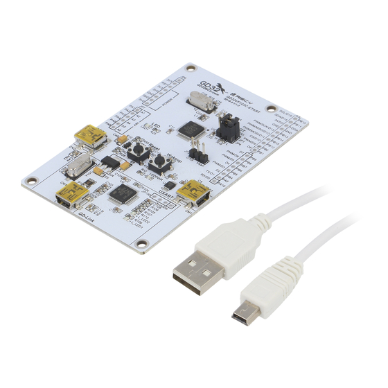
User Guide GD32VF103R-START Summary GD32VF103R-START uses GD32VF103RBT6 as the main controller. It uses Mini USB interface to supply 5V power. Reset, Boot, Wakeup key, LED, GD-Link and Ardunio are also included. Function Pin Assign Table 2-1 Function pin assignment Function... -
Page 6: Hardware Layout Overview
User Guide GD32VF103R-START Hardware layout overview 4.1. Power supply Figure 4-1 Schematic diagram of power supply DC-10B +U5V SW-SPDT +3V3 +5V0 LM1117-3.3 LEDPWR 16V/10uF,AVX 16V/10uF,AVX Vout 470Ω LED0603 SMD1210P005TF 50V/0.1uF 50V/0.1uF 4.2. Boot option Figure 4-2 Schematic diagram of boot option 4.3. -
Page 7: Key
User Guide GD32VF103R-START 4.4. Figure 4-4 Schematic diagram of Key function +3V3 K-1102B 10KΩ 50V/0.01uF 4.5. USBFS Figure 4-5 Schematic diagram of USBFS 47KΩ S8550 470R +U5V 16V/10uF,AVX 50V/0.1uF USB_VBUS VBUS PA11 USB_DM PA12 USB_DP Shield Mini_USB 1MΩ 50V/4700pF 4.6. -
Page 8: Extension
User Guide GD32VF103R-START MCU SWD PA0-WKUP +3V3 JP100 PB2/BOOT1 PB3/JTDO L_SWDIO L_TMS/IO PB4/JNTRST L_SWDCK L_TCK/CLK L_TDO/SWO L_TDI 4× 1P2.54 L_USB_Ctr L_TReset L_LED1 LED0603 PA10 PB10 L_USB_DM PA11 PB11 L_USB_DP L_LED1 R109 470Ω PA12 PB12 L_SWDIO L_LED2 R110 470Ω PA13/JTMS/SWDIO PB13... -
Page 9: Mcu
User Guide GD32VF103R-START 4.8. Figure 4-8 Schematic diagram of MCU PA0-WKUP PB2/BOOT1 PB3/JTDO PB4/JNTRST PA10 PB10 PA10 PB10 PA11 PB11 PA11 PB11 PA12 PB12 PA12 PB12 PA13 PB13 PA13/JTMS PB13 PA14 PB14 PA14/JTCK PB14 PA15 PB15 PA15/JTDI PB15 OSC_IN OSC_IN/PD0... -
Page 10: Routine Use Guide
Learn to use SysTick to generate 1ms delay GD32VF103R-START board has two keys and four LEDs. The two keys are Reset key and User key. The LED1, LED2, LED3 and LED4 are controlled by GPIO. This demo will show how to use the User key to control the LED1. When press down the User Key, it will check the input value of the IO port. -
Page 11: Gpio_Key_Interrupt_Mode
Learn to use EXTI to generate external interrupt GD32VF103R-START board has two keys and four LEDs. The two keys are Reset key and User key. The LED1, LED2, LED3 and LED4 are controlled by GPIO. This demo will show how to use the EXTI interrupt line to control the LED1.When press down the User Key, it will produce an interrupt. -
Page 12: Usbfs_Device
User Guide GD32VF103R-START 5.5. USBFS_Device 5.5.1. CDC_ACM DEMO purpose This demo includes the following functions of GD32 MCU: Learn how to use the USBFS peripheral Learn how to implement USB CDC device START board has one USBFS interface. In this demo, the START board is enumerated as an USB virtual COM port, which was shown in device manager of PC as below. -
Page 13: Usbfs_Host
Learn the operation between the MSC host and the Udisk GD32VF103R-START board integrates the USBFS module, and the module can be used as a USB device, a USB host or an OTG device. This demo mainly shows how to use the USBFS... - Page 14 User Guide GD32VF103R-START DEMO Running Result Insert the OTG cable to the USB port, download the program <05_USBFS\Host\MSC_Host> to the START board and run. If an Udisk has been attached, the LED4 will be light on, indicating that the U disk is successfully connected.
-
Page 15: Revision History
User Guide GD32VF103R-START Revision history Table 6-1 Revision history Revision No. Description Date Initial Release Jun.05, 2019 Update the titles of chapter 5.5 and 5.6 Sept.18, 2019... - Page 16 Important Notice This document is the property of GigaDevice Semiconductor Inc. and its subsidiaries (the "Company"). This document, including any product of the Company described in this document (the “Product”), is owned by the Company under the intellectual property laws and treaties of the People’s Republic of China and other jurisdictions worldwide.
Need help?
Do you have a question about the GD32VF103R-START and is the answer not in the manual?
Questions and answers