Advertisement
Quick Links
Advertisement

Subscribe to Our Youtube Channel
Related Manuals for ASUNA 7100


Summary of Contents for ASUNA 7100
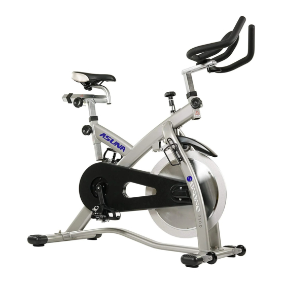
- Page 1 7100 Sabre Magnetic Commercial Indoor Cycling Bike Owner’s Manual Made in Taiwan...
-
Page 3: Table Of Contents
INDEX IMPORTANT SAFETY INFORMATION ..............1 EXPLODED DRAWING ..................... 2 PARTS LIST........................ 3 ASSEMBLY INSTRUCTION..................4-9 USER INSTRUCTION ....................10 MAINTENANCE ....................... 11 EXERCISE INSTRUCTION ................. 12-13 ATTENTION: Please verify that all parts associated with this product are in good condition and accounted for. -
Page 4: Important Safety Information
IMPORTANT SAFETY INFORMATION We thank you for choosing our product. To ensure your safety and health, please use this equipment correctly. It is important to read this entire manual before assembling and using the equipment. Safe and effective use can only be achieved if the equipment is assembled, maintained and used properly. -
Page 5: Exploded Drawing
Exploded Drawing... -
Page 6: Parts List
Parts list REF. Name REF. Name Seat Flywheel adjuster bolt Alloy bind clamp ( R &L ) Knob washer Spring for knob Plastic washer for knob Adjustment knob Knob fixed bolt Left crank arm Washer for knob Belt Seat slider Right crank arm Seat post Axle bolt for moving wheel... -
Page 7: Assembly Instruction
Assembly Instruction STEP: 1 Attach the Front Stabilizer (No. 16) and the Rear Stabilizer (No. 12) to the Main using 4 Bolts 10), 4 Washers 9) and 4 Nuts Frame (No. (No. (No. 8). Tighten and secure using spanner wrench. - Page 8 Assembly Instruction STEP: 2 Loosen Adjustment Knob (No. 4) on main frame handlebar tube to remove protection cap, then slide the Handlebar Post (No. 23) into the handlebar tube of the Main Frame (Y). Slide the Handlebar (No. 21) onto the Handlebar Post (No.
- Page 9 Assembly Instruction STEP: 3 Insert the Seat Post (No. 42) into the seat tube located on the Main Frame (Y). Insert the Seat Slider (No. 41) into the Seat Post (No. 42). Tighten the Adjustment Knob (No. 4) to secure the Seat Slider (No.
- Page 10 Assembly Instruction STEP: 4 IMPORTANT: Read instructions carefully, failure to do so may cause permanent damage to your bike. Connect Pedals L/R (No. 11) onto the Left and Right Crank Arms (No. 5 and 7). (Before you begin, immobilize the crank arms by turning the tension knob all the way to the right).
- Page 11 Assembly is complete!
- Page 12 Before beginning use of equipment, please be sure to inspect the entire bike carefully. Ensure that all moving and stationary parts have been properly installed and are operational. Inspect all screws, nuts and bolts as well to make sure that they are tightened and secure.
-
Page 13: User Instruction
User Instruction ASSEMBLY Properly assembling the equipment before use is very important. Be sure to follow all instructions as detailed in the assembly instructions section of the owner’s manual. ADJUSTING THE RESISTANCE Adjust the resistance of the bike using the Tension Knob. Increase the level of resistance by turning the tension knob to the RIGHT. -
Page 14: Maintenance
Maintenance IMPORTANT: Safe and effective use can only be achieved if the equipment is assembled, maintained and used properly. It is your responsibility to ensure that the equipment is maintained regularly. Any components found to be worn and/or damaged should be replaced before continuing use of the equipment.
Need help?
Do you have a question about the 7100 and is the answer not in the manual?
Questions and answers