Table of Contents
Advertisement
Quick Links
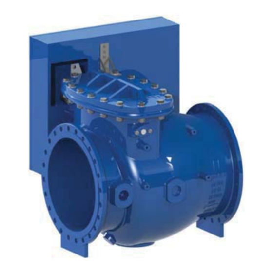
AVK SERIES 641 SWING CHECK VALVE
FIELD MAINTENANCE AND INSTRUCTION
MANUAL DN700 - DN1000
TABLE OF CONTENTS
EXPLODED ASSEMBLY / PARTS LIST
INSTALLATION
-
-
-
-
-
AVK GROUP A/S
An ISO 9001-2000 registered company
Maintenance Manual Series 641
*Subject to change without notice. (rev. 13/01 A)
Advertisement
Table of Contents

Related Manuals for AVK 641 Series


Summary of Contents for AVK 641 Series
-
Page 1: Table Of Contents
AVK SERIES 641 SWING CHECK VALVE FIELD MAINTENANCE AND INSTRUCTION MANUAL DN700 - DN1000 TABLE OF CONTENTS EXPLODED ASSEMBLY / PARTS LIST INTRODUCTION / DESCRIPTION HEALTH AND SAFETY AT WORK SPARE PARTS DESIGN CONSTRAINTS STORAGE AND HANDLING INSTALLATION SWING LEVER AND WEIGHT... - Page 2 AVK Series 641 Swingcheck Valve Exploded Parts Breakdown DN700 - DN1000 page 1...
- Page 3 AVK Series 641 Swingcheck Valve Exploded Parts Breakdown Parts List ITEM Description Material Hex Bolt SS EN 10088-1;A4 gr. 70 Washer SS ISO 3506; Grade A4 Cover DI EN 1563; GJS-500-7 Hinge Pin SS EN 10088-1;(W 1.4057) PA 6.6 (Polyamid) Ultramid A3K...
-
Page 4: Introduction / Description
This manual has been designed to assist, but it can never fully replace quality training in the workplace. However AVK Valves technical staff are always available to answer any questions relating to problems that may not be covered by this manual. -
Page 5: Storage And Handling
STORAGE AND HANDLING Storage higher than the dew point. If outdoor storage is unavoidable, valves should be supported off the ground and protected by a weather proof cover Handling INSTALLATION Correct installation of the Series 641 Check Valve is important for proper operation. It may be installed in either horizontal normal system operation. - Page 6 Front View Close position Direction of Flow Top View Fig.1 Horizontal Mountin page 5...
- Page 7 Close position Direction Flow Rear View Front View Fig.2 Vertical Mounting page 6...
- Page 8 open position Direction of Flow Horizontal Mounting open position Direction Flow Vertical Mounting Fig.3 Optimal Leverage Configurations page 7...
-
Page 9: Swing
INSTALLATION - continued: SWING LEVER AND WEIGHT (OPTIONAL) Once the valve is properly installed, the lever and weight assembly needs to be attached to the Hinge stem. Slide the Lever onto the Hinge stem and position as shown in figure 4. Secure the Lever with the Washer and Nut and tighten. Attach the Weight and tighten the hex screw and nut to hold the weight in place. -
Page 10: Lever, Weight And Guard
INSTALLATION - continued: LEVER WEIGHT AND GUARD (OPTIONAL) Once the valve is properly installed, install distance pipe and fasten the Back part guard by washers and bolts, then the lever and weight assembly needs to be attached to the Hinge stem. Slide the Lever onto the Hinges stem and position as shown in figure 5. -
Page 11: Free Shaft With Cover
INSTALLATION - continued: FREE SHAFT WITH COVER (OPTIONAL) Once the valve is properly installed, the protected cover needs to be attached to the hinge stem. Change the stud s t l t t i l c i t c i t Direction Gland flange Gland... -
Page 12: Proximity Switch
INSTALLATION - continued: PROXIMITY SWITCH (OPTIONAL) When the valve with outside shaft the valve can have a proximity switch option as figure 7 shown. Tighten the plate with set screw, put the proximity on position. When the valve without outside shaft, the valve can have a proximity switch option as figure 8 shown. The bracket for the proximity can be mounted on the cover. -
Page 13: Maintenance
MAINTENANCE AND INSPECTION MAINTENANCE: The valve is designed for underground use with little maintenance and no lubrication required. However, attention to the following points will ensure satisfactory working at all times. Removing the head assembly from the valve and examining the faces and moving parts for wear and if necessary, fitted as required. -
Page 14: Troubleshooting
TROUBLESHOOTING: Several problems and solutions are presented below to assist you in troubleshooting the valve. Gland flange Tightened the stud bolts on Gland flange. If leakage persists replace the between the Gland and bushing. O-cord on the body. Valve leaks when closed: Remove and inspect disc for damage. Replace if necessary. Ensure that the sealing surface in the valve body is clean and undamaged. -
Page 15: Disassembly For Inspection
DISASSEMBLY FOR INSPECTION: For convenience, the valve can be disassembled without removing it from the pipeline. All work on the valve should be performed by a skilled mechanic with proper tools and a hoist for larger valves. Disassembly may be required to inspect the disc for wear or the valve for deposits. -
Page 16: Reassembly After Inspection
REASSEMBLY AFTER INSPECTION: All parts and sealing surfaces must be cleaned before reassembly. Worn parts and seals should be replaced prior to reassembly.. Put the whole disc inside the body, make sure the disc facing to a proper direction. Put the higne stem in position, and tighten the set screw O-cord in the groove in the body if the O-cord need change.
Need help?
Do you have a question about the 641 Series and is the answer not in the manual?
Questions and answers