AVK 41 Series Installation, Operation And Maintenance Manual
Metal seat swing check valves, dn 350-600
Hide thumbs
Also See for 41 Series:
- Field maintenance and instruction manual (18 pages) ,
- Installation, operation and maintenance manual (18 pages) ,
- Installation, operation & maintenance manual (13 pages)
Table of Contents
Advertisement
Quick Links
Installation, Operation and Maintenance Manual -
Original Version
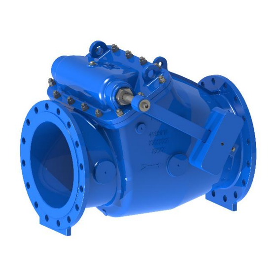
AVK Series 41, Metal Seat Swing Check Valves, DN 350-600
The AVK series 41 swing check valves are installed in water supply and wastewater
lines to make water flow in only one direction.
Flow reversal can occur for different reasons, like e.g. pump stop in a plant with large
differences in altitude, but with a check valve in the line this can be effectively
controlled.
Page 1 of 15
Copyright © AVK Holding A/S, original version, rev. 1, 21-Jan-2023
Advertisement
Table of Contents

Related Manuals for AVK 41 Series


Summary of Contents for AVK 41 Series
- Page 1 Original Version AVK Series 41, Metal Seat Swing Check Valves, DN 350-600 The AVK series 41 swing check valves are installed in water supply and wastewater lines to make water flow in only one direction. Flow reversal can occur for different reasons, like e.g. pump stop in a plant with large differences in altitude, but with a check valve in the line this can be effectively controlled.
-
Page 2: Avk Series 41, Dn 350-600, Exploded View
AVK series 41, DN 350-600, exploded view Page 2 of 15 Copyright © AVK Holding A/S, original version, rev. 1, 21-Jan-2023... -
Page 3: Avk Series 41, Dn 350-600, Parts List
Shock absorber EPDM Bolt Stainless steel Washer Stainless steel Guide bush EPDM Capscrew Stainless steel Tab washer Stainless steel Washer Stainless steel Valve body Ductile iron Page 3 of 15 Copyright © AVK Holding A/S, original version, rev. 1, 21-Jan-2023... -
Page 4: Table Of Contents
9.3 Disassembly for inspection and cleaning ..............13 9.4 Renewal of shaft and bushings ................. 13 Decommissioning ......................14 Trouble shooting ......................14 Recommended spare parts ..................... 15 Head Loss ........................15 Page 4 of 15 Copyright © AVK Holding A/S, original version, rev. 1, 21-Jan-2023... -
Page 5: Principle Of Operation
AVK’s products are designed to be fit for purpose and to a high reliability standard. This provides a safe, low risk product when used correctly for the purpose for which it was designed. -
Page 6: Receiving And Storage
Storage shall be under dry, cool conditions, away from direct sunlight and corrosive or otherwise chemically active atmosphere. Page 6 of 15 Copyright © AVK Holding A/S, original version, rev. 1, 21-Jan-2023... -
Page 7: Installation And Commissioning
M24 / M27 200-250 DN 450 M24 / M27 200-250 DN 500 M24 / M30 200-300 DN 600 M27 / M30 250-300 Table 1, Flange bolts torque values Page 7 of 15 Copyright © AVK Holding A/S, original version, rev. 1, 21-Jan-2023... -
Page 8: Flow Direction
Lever and weight must be adjusted according to the application. If the flow is low the least aggressive position will most often be used, i.e. the one that requires low pressure to open initially, but high pressure to keep wide open. Page 8 of 15 Copyright © AVK Holding A/S, original version, rev. 1, 21-Jan-2023... -
Page 9: Adjusting Lever And Weight
On some variants the lever in fully open position can pass the vertical point and drop down on the other side leaving the valve inoperable. In that case the aggressive position cannot be used. Page 9 of 15 Copyright © AVK Holding A/S, original version, rev. 1, 21-Jan-2023... - Page 10 Position 4 must in any case be expected to react very slowly from maximum flow. Fig. 5, Downwards flow, pos. 3 Page 10 of 15 Copyright © AVK Holding A/S, original version, rev. 1, 21-Jan-2023...
-
Page 11: Installation Of Lever And Weight
Fit the polyamide spacers, 3 short and 1 long, and install first the back part guard followed by the lever and weight and finally the front part of the guard. Fig. 7, Protection Guard Page 11 of 15 Copyright © AVK Holding A/S, original version, rev. 1, 21-Jan-2023... -
Page 12: Application Hazards
Check by-pass and priming device for leakage, if installed If the shaft seals leak in the bushings, check that they are properly tightened. If the leak persists, replace the O-rings. Page 12 of 15 Copyright © AVK Holding A/S, original version, rev. 1, 21-Jan-2023... -
Page 13: Disassembly For Inspection And Cleaning
O-rings (2, 3), bushings (1, 12) and shaft (5) are likely to be worn over time if the valve is operating constantly. Replace as necessary. Fig. 8, Top parts, shaft and bushings Page 13 of 15 Copyright © AVK Holding A/S, original version, rev. 1, 21-Jan-2023... -
Page 14: Decommissioning
When decommissioning the valve, it should be disposed of according to local regulations and in a way that allows as much recycling of materials as possible. AVK series 41 check valves do not contain hazardous substances that require special treatment. -
Page 15: Recommended Spare Parts
12. Recommended spare parts Only genuine AVK spare parts should be used. AVK accepts no responsibility for damage caused by failing non-AVK parts. Following spare parts are recommended to purchase with a ser. 41 valve: O-rings for shaft Bonnet gasket...
Need help?
Do you have a question about the 41 Series and is the answer not in the manual?
Questions and answers