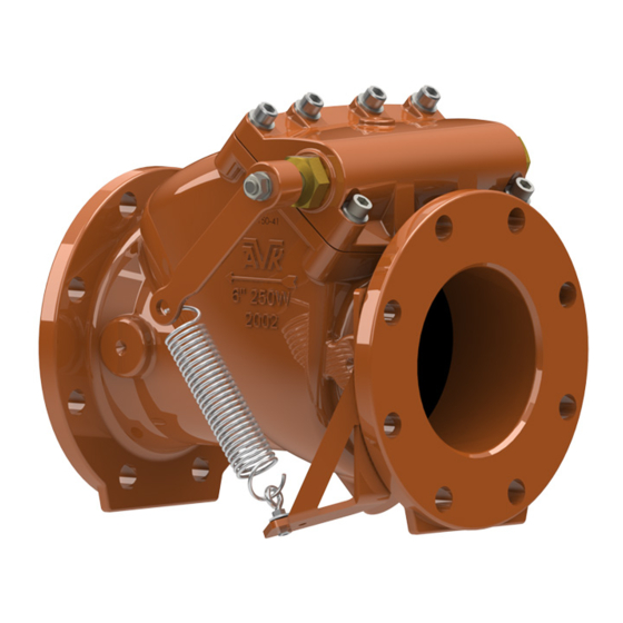
AVK 41 Series Field Maintenance And Instruction Manual
Swing check valve
Hide thumbs
Also See for 41 Series:
- Installation, operation and maintenance manual (18 pages) ,
- Installation, operation & maintenance manual (13 pages) ,
- Operation and maintenance instructions (10 pages)
Table of Contents
Advertisement
Quick Links
AVK SERIES 41 SWING CHECK VALVE
FIELD MAINTENANCE AND INSTRUCTION
MANUAL FOR SWING CHECK VALVES 3" - 12"
TABLE OF CONTENTS
EXPLODED ASSEMBLY / PARTS LIST
INTRODUCTION / DESCRIPTION
RECEIVING AND STORAGE
INSTALLATION
-
SWING
-
LEVER AND WEIGHT
-
LEVER AND SPRING
MAINTENANCE
TROUBLESHOOTING
DISASSEMBLY FOR INSPECTION
RE-ASSEMBLY AFTER INSPECTION
REPAIR PROCEDURES
-
HEAD REPLACEMENT
-
SEAL REPAIR KIT
-
SEAL/DISC KIT
OPTIONAL EQUIPMENT
-
PRIMING/BACKFLOW ACTUATOR (OPTIONAL, 3-inch through 8-inch)
PARTS AND SERVICE
WARRANTY
American AVK Company
An ISO 9001 registered company
Maintenance Manual Series 41
*Subject to change without notice. (rev. 06/20 H)
Advertisement
Table of Contents

Summary of Contents for AVK 41 Series
- Page 1 AVK SERIES 41 SWING CHECK VALVE FIELD MAINTENANCE AND INSTRUCTION MANUAL FOR SWING CHECK VALVES 3" - 12" TABLE OF CONTENTS EXPLODED ASSEMBLY / PARTS LIST INTRODUCTION / DESCRIPTION RECEIVING AND STORAGE INSTALLATION SWING LEVER AND WEIGHT LEVER AND SPRING...
- Page 2 page 1...
- Page 3 Stainless Steel For individual part ordering, refer to the item number, size & configuration of the valve when contacting American AVK Customer Services Note: Items (#401) through (#423) may be ordered as a replacement kit. ( Head Assembly ) Refer to "HEAD REPLACEMENT" on page 13.
-
Page 4: Introduction / Description
INTRODUCTION / DESCRIPTION The American AVK Series 41 Swing Check Valve is designed to be a trouble free, easy to maintain check valve. This manual will provide you with the information needed to properly install and maintain the valve and to ensure a long service life. The valve is opened by fluid flow in one direction and closes automatically to prevent flow in the reverse direction. - Page 5 Front View Direction of Flow Top View Fig. 2 Horizontal Mounting page 4...
- Page 6 Direction Flow Rear View Front View Fig. 3 Vertical Mounting page 5...
- Page 7 Open Position Direction of Flow Closed Position Horizontal Mounting Open Position Closed Position Direction Flow Vertical Mounting Fig. 4 Optimal Leverage Configurations page 6...
- Page 8 INSTALLATION - continued: SWING A valve without a lever is referred to as ‘Swing’. For Swing installation, follow the "INSTALLATION" instructions on page 3 . LEVER AND WEIGHT (OPTIONAL) Once the valve is properly installed, the lever and weight assembly needs to be attached to the Shaft (408) passing through the Open Bushing (417) in the Bonnet (407).
- Page 9 INSTALLATION - continued: LEVER AND SPRING 3"- 8" (OPTIONAL) For sizes 3-inch through 8-inch, the Spring Bracket (428) must be installed using the flange mounting hardware (figure 6). Install the Spring Eyebolt (425) on the Spring Bracket, securing it with the Spring Eyebolt Nuts (426), and Spring Eyebolt Washers (427), one washer and nut on each side of the Spring Bracket (428).
- Page 10 INSTALLATION - continued: LEVER AND SPRING 10"-12" (OPTIONAL) For Lever and Spring equipped 10-inch and 12-inch swing check valves, the Lever and Spring Assembly is installed at the factory. 422 412 429 407 430 409 423 413 408 431 432 417 418 416 415 414 433 434 435 436 424 426 425 437 427 428 Bent Tab on...
-
Page 11: Maintenance And Inspection
MAINTENANCE AND INSPECTION The AVK Series 41 Check Valve requires no scheduled lubrication or maintenance. The valve can be serviced or inspected without removal of the valve body from the line. INSPECTION: If inspection of the valve is required, follow the DISASSEMBLY FOR INSPECTION Instructions. - Page 12 DISASSEMBLY FOR INSPECTION: For convenience, the valve can be disassembled without removing it from the pipeline. All work on the valve should be performed by a skilled mechanic with proper tools and a hoist for larger valves. Disassembly may be required to inspect the disc for wear or the valve for deposits.
- Page 13 REASSEMBLY AFTER INSPECTION: All parts and sealing surfaces must be cleaned before reassembly. Worn parts and seals should be replaced prior to reassembly.. Lay the head assembly upside down on a clean surface so that the disc is up. Place the Bonnet Gasket (412) in the groove in the Bonnet (407). Place a Bonnet Bolt Washer (405) on each of the Bonnet Bolts (406).
-
Page 14: Repair Procedures
Failure to do so may cause pressure to be released resulting in severe injury or death. HEAD REPLACEMENT: AVK can supply a complete head assembly for easy replacement. When ordering a new head assembly, please refer to the check list below. AVK Series 41 Head Assembly Ordering Checklist... - Page 15 REPAIR PROCEDURES - continued: SEAL REPAIR KIT: The Seal Repair Kit consists of two (2) Inner Bushing O-rings (418), two (2) Bonnet O-rings (429). The Inner Bushing O-rings are not used on valves without a lever. 10-inch and 12-inch valves have Bonnet O-rings (429). Remove the head assembly as described under DISASSEMBLY FOR INSPECTION above.
- Page 16 SEAL/DISC KIT: For 3-inch through 8-inch valves, the Seal/Disc Repair Kit consists of two (2) Inner Bushing O-rings (418), two (2) Bonnet O-rings (429), and one (1) Bonnet Gasket (412), one (1) Disc (413), one (1) Disc Bushing (403), one (1) Disc Washer (402), one Disc Lock Washer (423)*, and one (1) Disc Nut (401).
-
Page 17: Parts And Service
PARTS AND SERVICE For information on parts and service for your area contact American AVK. Make a note of the valve model number and size located on the valve and contact: American AVK Company 2155 N. Meridian Blvd Minden, NV 89423... - Page 18 NOTES: page 17...


Need help?
Do you have a question about the 41 Series and is the answer not in the manual?
Questions and answers