AVK 41 Series Installation, Operation And Maintenance Manual
Swing check valves, dn 50-300
Hide thumbs
Also See for 41 Series:
- Field maintenance and instruction manual (18 pages) ,
- Installation, operation and maintenance manual (15 pages) ,
- Installation, operation & maintenance manual (13 pages)
Table of Contents
Advertisement
Quick Links
Installation, Operation and Maintenance Manual -
Original Version
AVK Series 41, Swing Check Valves, DN 50-300
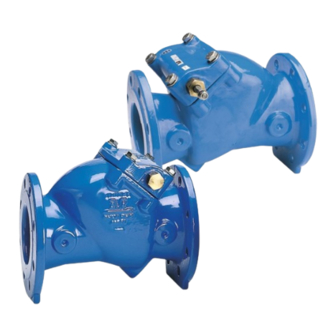
The AVK series 41 swing check valves are installed in water supply and wastewater
lines to make water flow in only one direction.
Flow reversal can occur for different reasons, like e.g. pump stop in a plant with large
differences in altitude, but with a check valve in the line this can be effectively
controlled.
Valves in the size range DN 50-300 come as both resilient and metal seated with the
resilient seated having a rubber face pressing against the cast iron seat and the metal
seats consisting of copper alloy face- and seat rings.
Page 1 of 18
Copyright © AVK Holding A/S, original version, rev. 1, 21-Jan-2023
Advertisement
Table of Contents

Related Manuals for AVK 41 Series


Summary of Contents for AVK 41 Series
- Page 1 Original Version AVK Series 41, Swing Check Valves, DN 50-300 The AVK series 41 swing check valves are installed in water supply and wastewater lines to make water flow in only one direction. Flow reversal can occur for different reasons, like e.g. pump stop in a plant with large differences in altitude, but with a check valve in the line this can be effectively controlled.
-
Page 2: Avk Series 41, Swing Check Valves, Exploded View
AVK series 41, swing check valves, exploded view Page 2 of 18 Copyright © AVK Holding A/S, original version, rev. 1, 21-Jan-2023... -
Page 3: Avk Series 41, Parts List
Inner Bushing O-rings EPDM 41 Seat Ring, Disc Part Bronze Weight Cast iron 42 Seat Ring, Body Part Bronze Item 31-40 refer to Fig. 10, DN250-300 only Page 3 of 18 Copyright © AVK Holding A/S, original version, rev. 1, 21-Jan-2023... -
Page 4: Table Of Contents
Table of contents AVK series 41, swing check valves, exploded view ............2 AVK series 41, parts list ....................3 Table of contents ....................... 4 Principle of operation ......................5 Health and safety at work ....................6 Receiving and storage ....................... 7 Installation and commissioning .................. -
Page 5: Principle Of Operation
Dutile Iron Valve Body Gunmetal / Stainless Steel / DI Disc EPDM Rubber Encapsulation Copper alloy Seat Ring, Disc Part Copper alloy Seat Ring, Body Part Page 5 of 18 Copyright © AVK Holding A/S, original version, rev. 1, 21-Jan-2023... -
Page 6: Health And Safety At Work
AVK’s products are designed to be fit for purpose and to a high reliability standard. This provides a safe, low risk product when used correctly for the purpose for which it was designed. -
Page 7: Receiving And Storage
Storage shall be under dry, cool conditions, away from direct sunlight and corrosive or otherwise chemically active atmosphere. Page 7 of 18 Copyright © AVK Holding A/S, original version, rev. 1, 21-Jan-2023... -
Page 8: Installation And Commissioning
DN 150 M20 / M20 DN 200 M20 / M20 DN 250 M20 / M24 DN 300 M20 / M24 Table 1, Flange bolts torque values Page 8 of 18 Copyright © AVK Holding A/S, original version, rev. 1, 21-Jan-2023... -
Page 9: Flow Direction
Page 9 of 18 Copyright © AVK Holding A/S, original version, rev. 1, 21-Jan-2023... -
Page 10: Adjusting Lever And Weight
On some variants the lever in fully open position can pass the vertical point and drop down on the other side leaving the valve inoperable. In that case the aggressive position cannot be used. Page 10 of 18 Copyright © AVK Holding A/S, original version, rev. 1, 21-Jan-2023... - Page 11 Position 4 must in any case be expected to react very slowly from maximum flow. Fig. 7, Downwards flow, pos. 3 Page 11 of 18 Copyright © AVK Holding A/S, original version, rev. 1, 21-Jan-2023...
-
Page 12: Installation Of Lever And Weight
To adjust closing speeds for optimum performance the weight can be moved on the lever in order to change the torque applied to the shaft, hinge and disc. Fig. 8, Weight Components Page 12 of 18 Copyright © AVK Holding A/S, original version, rev. 1, 21-Jan-2023... -
Page 13: Lever And Spring, Dn200 And Below (Optional)
Slide the lever (17) onto the shaft (9) and position as shown in figure 8. Secure the lever with the shaft washer (16) and shaft nut (15) and tighten to 40Nm. Attach the spring (25). Fig. 9, Spring adjustment, DN≤200 Page 13 of 18 Copyright © AVK Holding A/S, original version, rev. 1, 21-Jan-2023... -
Page 14: Lever And Spring, Dn250-300 (Optional)
304 Stainless steel Spring Arm Spacer Stainless Steel Spring Stainless Steel Shaft Lock Washer Stainless Steel Spring Eyebolt Stainless Steel Spring Bracket Mount Washer Stainless Steel Page 14 of 18 Copyright © AVK Holding A/S, original version, rev. 1, 21-Jan-2023... -
Page 15: Application Hazards
Check by-pass and priming device for leakage, if installed If the shaft seals leak in the bushings, check that they are properly tightened. If the leak persists, replace the O-rings. Page 15 of 18 Copyright © AVK Holding A/S, original version, rev. 1, 21-Jan-2023... -
Page 16: Disassembly For Inspection And Cleaning
O-rings (19, 30), bushings (4, 18, 23) and shaft (9) are likely to be worn over time if the valve is operating constantly. Replace as necessary. Fig. 11, Shaft and bushings Page 16 of 18 Copyright © AVK Holding A/S, original version, rev. 1, 21-Jan-2023... -
Page 17: Decommissioning
When decommissioning the valve it should be disposed of according to local regulations and in a way that allows as much recycling of materials as possible. AVK series 41 check valves do not contain hazardous materials that require special treatment. 11. Trouble shooting... -
Page 18: Recommended Spare Parts
12. Recommended spare parts Only genuine AVK spare parts should be used. AVK cannot accept responsibility for damage caused by failing non-AVK parts. Following spare parts are recommended to purchase with a ser. 41 valve: O-rings for shaft Bonnet gasket...
Need help?
Do you have a question about the 41 Series and is the answer not in the manual?
Questions and answers