
Related Manuals for R.V.R. Electronica VJ3000


Summary of Contents for R.V.R. Electronica VJ3000
- Page 1 VJ3000 T E C H N I C A L A N D M A I N T E N A N C E M A N U A L MANUALETECNICOEDIMANUTENZIONE M a n u f a c t u r e d b y R . V . R . E l e t t r o n i c a - I t a l y...
- Page 2 VJ3000 - Technical and Maintenance Manual VJ3000 3KW Power Triode Amplifier 87.5-108 MHz Technical and Maintenance Manual Manuale Tecnico e di Manutenzione English Pag. 3 Italiano Pag. 88 R.V.R. ELETTRONICA S.r.l. (BO) Pag. 2...
-
Page 3: Table Of Contents
VJ3000 - Technical and Maintenance Manual INDEX Preliminary Instructions and Warranty Information Pag. 6 Tube Warranty Instructions Pag. 8 Safety Regulations Pag. 11 SECTION 1 General Description Pag. 14 Electrical Specifications (Table A) Pag. 16 Dimensional & Environmental Specifications (Table B) Pag. - Page 4 VJ3000 - Technical and Maintenance Manual Power Supply Input sockets - Three-Phase Ver.(Fig. 8B) Pag. 44 Sectional View Descrip. of the Power Supply P2 - Mono-Phase Ver. Pag. 45 Sectional View of the Power Supply P2 - Mono-Phase Ver. (Fig. 8C) Pag.
-
Page 5: Table Of Contents
VJ3000 - Technical and Maintenance Manual SECTION 4 Maintenance Pag. 76 SECTION 5 Calibration Procedure of Modules Pag. 78 Setup 4 Pag. 82 Setup 5 Pag. 83 Setup 6 Pag. 84 Setup 7 Pag. 85 Setup 8 Pag. 86 Setup 9 Pag. -
Page 6: Preliminary Instructions And Warranty Information
VJ3000 - Technical and Maintenance Manual PRELIMINARY INSTRUCTIONS AND WARRANTY INFORMATION WARNING: This is a "CLASS A" equipment. In a residential place this equipment can cause hash. In this case can be requested to user to take the necessari measures. - Page 7 VJ3000 - Technical and Maintenance Manual To claim your rights under this warranty: Contact the dealer or distributor where you prchased the unit. Describe the problem and ask if he has an easy solution. Dealers and Distributors are supplied with all the information about problems that may occur and usually they can repair the unit quicker than what the manufacturer could do.
-
Page 8: Tube Warranty Instructions
VJ3000 - Technical and Maintenance Manual TUBE WARRANTY INSTRUCTIONS VARIAN POWER GRID PRODUCT LIMITED WARRANTY Varian products are warranted to be free from defects in workmanship and materials only. The warranty involves both calendar time and filament (or heather) operation time. Specifically involved are: time since the product was shipped from Varian time since delivery to the user, and operation time. - Page 9 VJ3000 - Technical and Maintenance Manual will be calculated and credit issued. This can only be done through the original OEM or authorized Varian Distributor. A prorated credit is calculated as follows: Warranty (hours) - Use Time (hours) = % Credit...
- Page 10 VJ3000 - Technical and Maintenance Manual WARRANTY OF THE DIFFERENT TYPE OF TUBES MODEL MOUNTH HOURS CODE 3CX800A7 3.000 3CX1500A7 3.000 3CX3000A7 5.000 3CX15000A7 3.000 4CX3500A 5.000 4CX5000A 10.000 4CX7500A 5.000 4CX10000D 10.000 R.V.R. ELETTRONICA S.r.l. (BO) Pag. 10...
-
Page 11: Safety Regulations
VJ3000 - Technical and Maintenance Manual WARNING! The currents and voltages in this equipment are dangerous! Personnel must at all times observe safety regulation! This manual is intended as a general guide for trained and qualified personnel who are aware of the dangers inherent in handling potentially hazardous electrical and electronic circuits. - Page 12 VJ3000 - Technical and Maintenance Manual TreatmentofelectricalShock 1) If victim is not responsive follow the A-B-C's of basic life support. PLACE VICTIM FLAT ON HIS BACK ON A HARD SURFACE A A I R W A Y BBREATHING IF UNCONSCIOUS,...
- Page 13 VJ3000 - Technical and Maintenance Manual FIRST-AID Personnelengagedintheinstallation,operation,maintenanceor servicingofthisequipmentareurgedtobecomefamiliarwithfirst-aid theoryandpractices.Thefollowinginformationisnotintendedtobe acompletefirst-aidprocedure,itisbriefandisonlytobeusedas areference.Itisthedutyofallpersonnelusingtheequipmenttobe preparedtogiveadequateEmergencyFirstAidandtherebyprevent avoidablelossoflife. Treatment of electrical Burns 1) Extensive burned and broken skin. Cover area with clean sheet or cloth. (Cleanest available cloth article). Do not break blisters, remove tissue, remove adhered particles clothing, or apply any salve or ointment.
-
Page 14: General Description
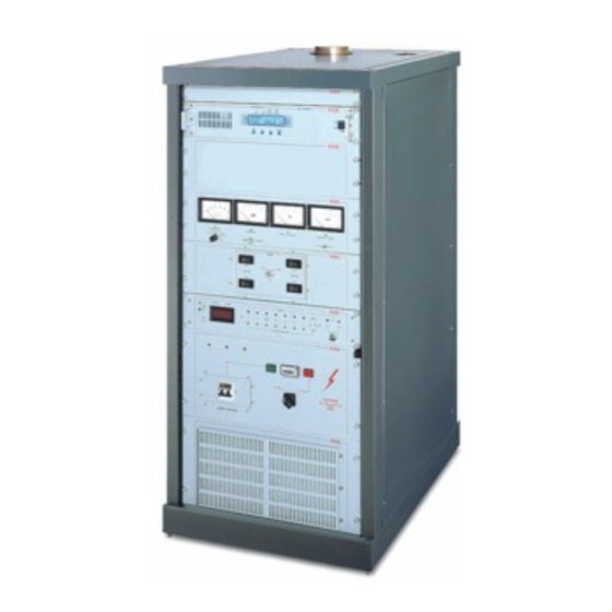
VJ3000 1.1 MECHANICAL DESCRIPTION The VJ3000 is housed in a 19" rack cabinet, 24U high, of which 6 are free and may be used to fit an exciter, a receiver and other equipment. Four analog meters are situated on the front panel (Fig. 1A) together with all the various controls and switches. - Page 15 VJ3000 - Technical and Maintenance Manual Three indicators show the presence of three phases (R, S and T) for the Threephase version and the presence of the single phase for the Monophase version. 1.4 PROTECTION FEATURES The alarm panel (Fig.5 has a number of indicators of different colors: the red indicators indicate a current condition, the yellow indicators show that a previous alarm condition has now passed.
-
Page 16: Electrical Specifications
VJ3000 - Technical and Maintenance Manual TABLE A ELECTRICAL SPECIFICATIONS Supply Monophase: 220-240V, 50-60 Hz Threephase: 380-415V, 50-60 Hz (on request) Frequency Range 87.5-108Mhz (others on request) Output Power 3500W max, 3000W typically R.F. Output Impedance 50 Ohm R.F. Output Connector 7/8"... -
Page 17: Mechanical Specifications
VJ3000 - Technical and Maintenance Manual TABLE B MECHANICAL SPECIFICATIONS Rack Dimensions 22.24" (565 mm) W 33.46" (850 mm) D 48.00" (1220 mm) H Panel Dimensions 19" (483.00 mm) W 42" (1066.8 mm) H Weight 770 Lbs (350 Kg) Operating Temperature from -10°C to +50°C... -
Page 18: Electrical Description
VJ3000 - Technical and Maintenance Manual SECTION 2 ELECTRICAL DESCRIPTION 2.1 INTRODUCTION This chapter describes, in detail, the operating theory of the VJ3000. To aid understanding, the unit has been subdivided into modules (Fig.2), each of which is fully described below. - Page 19 VJ3000 - Technical and Maintenance Manual 1KW) that ensures the stability of the tube filament voltage. 2.3 HIGH VOLTAGE POWER SUPPLY A) THREEPHASE VERSION This sub-assembly (P2 fig.8A) is situated at the bottom of the unit and comprises: a transformer T2 (5 Fig.8A) to supply the anode voltage (6KV);...
- Page 20 VJ3000 - Technical and Maintenance Manual the protection system re-enables the unit unless the fault is still present, in which case the cycle is repeated upto a maximum of 11 times, after which the unit is shutdown indefinately. At this point only manual or remote intervention can restart the unit.
- Page 21 VJ3000 - Technical and Maintenance Manual frequency. In the central section of the chamber, around the tube socket, is situated a collar with fingers to ground the control grid. Two disks are also situated in this section of the chamber, on the left-...
- Page 22 VJ3000 - Technical and Maintenance Manual TABLE C SPECIFICATIONS OF THE 3CX3000A7 TUBE Model 3CX3000A7 Anode dissipation 3000W Grid dissapation 225W Frequency for max. ratings (CW) 110Mhz Cooling Forced ventilation Filament voltage 7.5V Filament current 51.5A Capacity with grounded cathode: Input 38.0 pF...
-
Page 23: Front And Rear View (Fig. 1A)
VJ3000 - Technical and Maintenance Manual FRONT AND REAR VIEW (FIG.1A) ....Free panels 6U ....Meter panel ....Tuning panel ....Protections panel ....High voltage panel ....Front air filter panel ....Blower air filter ....Power supply input holes R.V.R. - Page 24 VJ3000 - Technical and Maintenance Manual FIG.1A R.V.R. ELETTRONICA S.r.l. (BO) Pag. 24...
-
Page 25: Top View (Fig. 1B)
VJ3000 - Technical and Maintenance Manual TOP VIEW (FIG.1B) ....Air-flow chimney ....R.F. output connector R.V.R. ELETTRONICA S.r.l. (BO) Pag. 25... - Page 26 VJ3000 - Technical and Maintenance Manual FIG.1B R.V.R. ELETTRONICA S.r.l. (BO) Pag. 26...
-
Page 27: Total View (Fig. 2)
VJ3000 - Technical and Maintenance Manual TOTAL VIEW (FIG.2) ....R.F. Chamber ....Inductance ....Power supply P1 section ....Power supply P2 section ....Blower ....Air-flow chimney R.V.R. ELETTRONICA S.r.l. (BO) Pag. 27... -
Page 28: R.v.r. Elettronica S.r.l. (Bo)
VJ3000 - Technical and Maintenance Manual FIG.2 R.V.R. ELETTRONICA S.r.l. (BO) Pag. 28... - Page 29 VJ3000 - Technical and Maintenance Manual FRONT METER PANEL (FIG.3) VOLTAGE SELECTOR Mechanical adjustment of the zero point of the multmeter. MULTMETER ADJUSTMENT Mechanical adjustment of the zero point of the multmeter GRID CURRENT SELECTOR Switch to select the measurement of the grid current Ig1 or Ig2 (Ig2 not connected in the Triode Version).
- Page 30 VJ3000 - Technical and Maintenance Manual FIG.3 R.V.R. ELETTRONICA S.r.l. (BO) Pag. 30...
- Page 31 VJ3000 - Technical and Maintenance Manual FRONT TUNING PANEL (FIG.4) INPUT Press-button INPUT for tuning of the input circuit. LOAD Press-button for tuning the load. SWITCH Switch enabling the tuning motors. PLATE Press-button PLATE for tuning the anode. GRID Press-button GRID for tuning of the input circuit.
- Page 32 VJ3000 - Technical and Maintenance Manual FIG.4 R.V.R. ELETTRONICA S.r.l. (BO) Pag. 32...
- Page 33 VJ3000 - Technical and Maintenance Manual FRONT AND REAR PROTECTION PANEL (FIG.5) RESET Switch to reset the ALARMS MEMORY and the protection counter. DISPLAY The two right-hand digits display the air outlet temperature The two letf-hand digits display the number of protection cycles. When the TIM/CICL button is pushed these digits display the percentage of the filament warm-up period that has passed.
- Page 34 VJ3000 - Technical and Maintenance Manual amplifier. LED AUTO Led indicating that protection is active. DISCONNECT Led indicating that the selector has been rotated to the DISCONNECT position and that protection will be disabled for about 1 minute. PWR FWD...
- Page 35 VJ3000 - Technical and Maintenance Manual FIG.5 R.V.R. ELETTRONICA S.r.l. (BO) Pag. 35...
- Page 36 VJ3000 - Technical and Maintenance Manual FRONT HIGH VOLTAGE PANEL (FIG.6) MAIN Line power switch (thermal cutout). INDICATOR ON Green indicator showing the presence of line power. HUOR METER Hour counter showing the total number of hours that the unit has been operational.
- Page 37 VJ3000 - Technical and Maintenance Manual FIG.6 R.V.R. ELETTRONICA S.r.l. (BO) Pag. 37...
- Page 38 VJ3000 - Technical and Maintenance Manual SECTIONAL VIEW OF THE POWER SUPPLY P1 (FIG.7A) THREE-PHASE VERSION ....PROT-IN card ....Services transformer diode bridge, D13 ....Grid current sensing resistor, R6 ....IG Triode card ....Plate Measure card ....
- Page 39 VJ3000 - Technical and Maintenance Manual 14 13 12 11 FIG.7A R.V.R. ELETTRONICA S.r.l. (BO) Pag. 39...
- Page 40 VJ3000 - Technical and Maintenance Manual SECTIONAL VIEW OF THE POWER SUPPLY P1 (FIG.7B) MONO-PHASE VERSION ....PROT-IN card ....Services transformer diode bridge, D13 ....Main services transformer (T1) ....Solenoid switch TE1 for filament voltage ....Solenoid switch TE2 for HT1 ....
- Page 41 VJ3000 - Technical and Maintenance Manual FIG.7B R.V.R. ELETTRONICA S.r.l. (BO) Pag. 41...
- Page 42 VJ3000 - Technical and Maintenance Manual SECTIONAL VIEW OF THE POWER SUPPLY P2 (FIG.8A) THREE-PHASE VERSION ....Threephase power connector block (MORS1) ....A.C. driver output connector block (MORS2) ....Anode supply bridge rectifier (D3, D4, D5, D6, D7 and D8) ....
- Page 43 VJ3000 - Technical and Maintenance Manual FIG.8A R.V.R. ELETTRONICA S.r.l. (BO) Pag. 43...
- Page 44 VJ3000 - Technical and Maintenance Manual TRHEE-PHASE VOLTAGE INPUT SOCKET (FIG.8B) R.V.R. ELETTRONICA S.r.l. (BO) Pag. 44...
- Page 45 VJ3000 - Technical and Maintenance Manual SECTIONAL VIEW OF THE POWER SUPPLY P2 (FIG.8C) MONO-PHASE VERSION ....Monophase power connector block (MORS1) ....A.C. driver output connector block (MORS2) ....Anode supply bridge rectifier (D3, D4, D5 and D6) ....
- Page 46 VJ3000 - Technical and Maintenance Manual FIG.8C R.V.R. ELETTRONICA S.r.l. (BO) Pag. 46...
- Page 47 VJ3000 - Technical and Maintenance Manual MONO-PHASE VOLTAGE INPUT SOCKET (FIG.8D) R.V.R. ELETTRONICA S.r.l. (BO) Pag. 47...
- Page 48 VJ3000 - Technical and Maintenance Manual R.F. CAVITY FRONT VIEW (FIG.9) ....Variable capacitor C5 (moving surface with fingers) ....Variable capacitor C6 (LOAD) ....Variable capacitor C34 for tuning at low frequency (if present) ....Tube socket ....Inductance L7 (L8) ....
- Page 49 VJ3000 - Technical and Maintenance Manual FIG.9 R.V.R. ELETTRONICA S.r.l. (BO) Pag. 49...
- Page 50 VJ3000 - Technical and Maintenance Manual R.F. CAVITY REAR VIEW (FIG.10) ....Filament Transformer (T5) ....Deviding Transformer (T4) ....Cooling blower (FAN1) ....Circular connector 28-pin (J1) ....Circular connector 28-pin (J2) ....Tuning motor INPUT (M2) R.F. CAVITY RIGHT SIDE VIEW (FIG.11)
Need help?
Do you have a question about the VJ3000 and is the answer not in the manual?
Questions and answers