
Subscribe to Our Youtube Channel
Related Manuals for AUTOHELM Masterview ST80


Summary of Contents for AUTOHELM Masterview ST80
- Page 1 ST80 Masterview D2601-1 Z211 ST80 Masterview Service Procedures ST80 Masterview Service Manual 83028-1 1...
- Page 2 CE requirements. Incorporation, use or attachment, by any means, of parts or components not supplied for or not approved for such use by Autohelm or, if supplied or approved for use by Autohelm, not properly fitted in accordance with...
-
Page 3: Table Of Contents
ST80 Masterview Contents 1. Description ..............5 2. Operation ..............5 3. Disassembly ..............6 4. Assembly ...............6 5. Functional Test ...............8 5.1 Preliminary Inspection ............8 5.2 Test Equipment ..............8 5.3 Functional Test Flowchart ............ 9 6. Spares Numbers ............11 7. - Page 4 ST80 Masterview 4 Masterview Service Manual 83028_1...
-
Page 5: Description
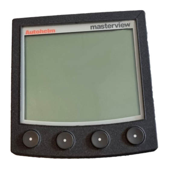
ST80 Masterview 1. Description The item covered by this section of the Maintenance Manual is the ST80 Masterview Head, Product Code Z211. Masterview is a multifunction instrument which displays SeaTalk data in alphanumeric and graphic formats. 2. Operation There are no operational activities required to set up or calibrate the Masterview for testing except as detailed in Chapter 5. -
Page 6: Disassembly
ST80 Masterview 3. Disassembly Refer to Figure 1, Exploded View. 1. Unscrew and remove the six No. 2 x 1/2 screws (6). Separate the rear cover (5) from the front cover (1) using the ST80 Case Separation Tool (T041). 2. If an ST80 Case Separation Tool is not available, separate the covers by hand. -
Page 7: Figure 1 Exploded View
ST80 Masterview 3. Assemble the rear cover (5) to the front cover. Hold the instrument in both hands face down and clear of the work surface. Use moderate thumb pressure, or preferably heel of the hand pressure which spreads the area of contact, to press the front cover into the rear cover a little at a time. -
Page 8: Functional Test
ST80 Masterview 5. Functional Test 5.1 Preliminary Inspection Before testing, inspect the instrument for physical damage (cracked or broken screen, case, bent connector pins, etc.). Take off the rear cover and check for signs of water ingress. Check for damage to the PCB, in particular, overheating on the power supply input and output pins and PCB tracks. -
Page 9: Functional Test Flowchart
ST80 Masterview 5.3 Functional Test Flowchart START CONNECT TEST EQUIPMENT SWITCH ON CHANGE PCB CHECK MASTERVIEW (3) & RESTART KEY IDENTIFICATION POWERED UP FOR FLOWCHART USE PRESS CHAPTER (A) AND CHANGE PCB PAGE (B) KEYS & RESTART TOGETHER FOR 2 SECONDS. CHECK DISPLAY SHOWS NOTE: THE DISPLAY MAY SETUP... - Page 10 ST80 Masterview 10 Masterview Service Manual 83028_1...
-
Page 11: Spares Numbers
ST80 Masterview 6. Spares Numbers Item Cat. No. Part No. Comments Printed Circuit Q154 Board Keypad Q149 ST80 Case T041 Separation Tool Front Cover W065 Rear Label W066 Rear Cover W067 ST80 Masterview Service Manual 83028-1 11... - Page 12 ST80 Masterview 12 Masterview Service Manual 83028_1...
-
Page 13: Circuit Description
7.2 External Signals SeaTalk SeaTalk signals from P3 or P6 are routed direct to the Autohelm ASIC IC4. Incoming signals are converted by the ASIC from SeaTalk duplex line format to Received Data (DATA Rx) format for the microprocessor. Outgo- ing signals are converted from DATA Tx format at CMOS voltage levels to SeaTalk format at 12V level by the ASIC. -
Page 14: Signal Processing
7.3 Signal Processing Microprocessor IC13 has a clock rate of 16MHz, determined by crystal XL1. External and internal inputs, SeaTalk data and signals from the Autohelm ASIC are processed and the appropriate commands and responses are generated by the microprocessor. - Page 15 Checks on the charge state of battery B1 are made by signal B_SENSE applied to transistor TR19, which generates signal B_LEVEL to ASIC IC4. Autohelm ASIC The ASIC is a custom-designed IC which provides specific facilities and functions. These are: 1.
-
Page 16: Figure 3 Block Diagram
ST80 Masterview TO EL PANEL DRIVERS TR23 PA.2 TR20 TO ELECTRO- VUNREG LUMINESCENT +12V PANEL TR23 REGULATOR VHELD TO ASIC IC4 +12V 0VEL VUNREG VCC (+5V) IC14 CONTRAST PA.4 TR12 IC16 NEGATIVE VOLTAGE CURRENT AMP & GENERATOR INTEGRATOR 0V EL TO EL PANEL DRIVERS VUNREG... -
Page 17: Figure 4 Circuit Diagram (Sheet 1)
ST80 Masterview Figure 4 Circuit Diagram (Sheet 1) ST80 Masterview Service Manual 83028-1 17... -
Page 18: Figure 5 Circuit Diagram (Sheet 2)
ST80 Masterview D2609-1 Figure 5 Circuit Diagram (Sheet 2) 18 Masterview Service Manual 83028_1... -
Page 19: Pcb Detail
ST80 Masterview 8. PCB Detail 8.1 PCB Layout Conventional Components, Surface Mount Components, component side component side Surface Mount Components, Conventional Components, underside underside Taken from Drawing No: 4280-001 Issue: Q Date:10.09.96 D2606-1 Figure 6 PCB Layout ST80 Masterview Service Manual 83028-1 19... -
Page 20: Pcb Component Lists
ST80 Masterview 8.2 PCB Component Lists Surface Mount Components, component side D3961-1 Taken from Drawing No: 4280-001 Issue: Q Date:10.09.96 Conventional Components, component side D3962-1 Taken from Drawing No: 4280-001 Issue: Q Date:10.09.96 20 Masterview Service Manual 83028_1... - Page 21 ST80 Masterview Surface Mount Components, underside D3963-1 Taken from Drawing No: 4280-001 Issue: Q Date:10.09.96 Conventional Components, underside D3964-1 Taken from Drawing No: 4280-001 Issue: Q Date:10.09.96 ST80 Masterview Service Manual 83028-1 21...
- Page 22 ST80 Masterview 22 Masterview Service Manual 83028_1...
Need help?
Do you have a question about the Masterview ST80 and is the answer not in the manual?
Questions and answers