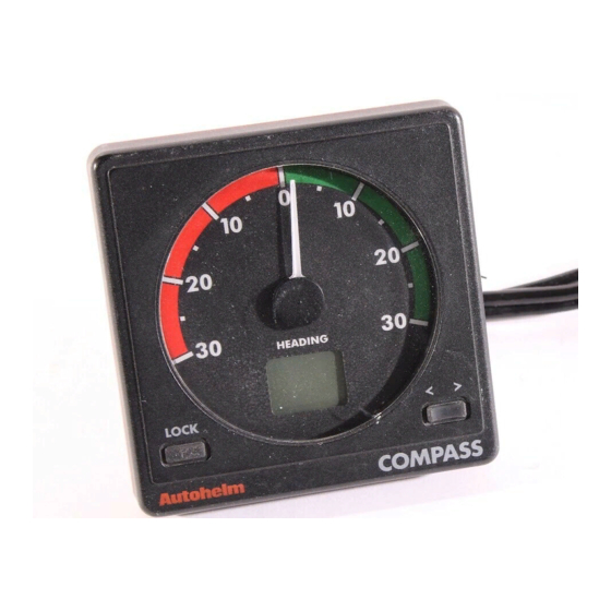
AUTOHELM SeaTalk ST50 Plus Operation And Installation
Wind & close hauled/vmg
Hide thumbs
Also See for SeaTalk ST50 Plus:
- User manual (17 pages) ,
- Operation and installation manual (39 pages) ,
- Operation and installation (47 pages)
Summary of Contents for AUTOHELM SeaTalk ST50 Plus
- Page 1 Distributed by Any reference to Raytheon or RTN in this manual should be interpreted as Raymarine. The names Raytheon and RTN are owned by the Raytheon Company.
- Page 2 Operation and installation...
- Page 3 The following items are included in the ST50 Plus Wind package: 1 . ST50 Plus Wtnd control head 2 . Fixing studs (2 offI 3. Thumb nuts (2 oftI 4. Fitting template 5. Power cable 6. Masthead transducer 7 . Control head cover 8.
-
Page 4: Table Of Contents
........Sing ................Mounting Procedure ............Power Supply (stand-alone operation) ........6 Power Supply (SeaTalk operation) ........6 Connection of Separated Instruments ........7 1.6 Ring Connection .............. 1.7 Connection to SeaTalk Compatible Autopilots ......8 2.1 Connection to the Control Head ........... 9 2.2 Masthead Transducer Installation ........ - Page 5 These instruments also incorporate a security feature to protect units mounted in vulnerable areas, such as the cockpit, helm or mast. Thank you for purchasing an Autohelm product. May we take this opportunity to wish you years of trouble free operation.
- Page 6 Chapter 1: Control Head Installation 1.1 siting The ST50 plus Wind is designed for above or below deck installation where it is: Easily read by the helmsman Protected against physical damage At least 230mm (9in)from a compass At least 500mm (2Oin) from radio receiving equipment Accessible from behind for ease of installation and cable running.
-
Page 7: Sing
The rear case is fitted with a foam gasket to form a water-tight seal between Bracket Mounting the instrument and the selected installation face. The ST50 Plus Wind can, as an alternative, be bracket mounted using the Because the instrument breathes through the vent in the rear case, this bracket is for interior use only. -
Page 8: Power Supply (Stand-Alone Operation)
1.5 Connection of Separated lnstnments Separated instruments can be connected using one of the range of SeaTalk Extension Cable. These cables are supplied with a SeaTalk connector fitted to each end. A junction box can be used to join the cable if it is cut for easier routing or shortening. -
Page 9: Connection To Seatalk Compatible Autopilots
Chapter 2: Transducer Installation Installations with a large number of instruments on a SeaTalk bus may require 2.1 Connection to the Control Head a second riigmain connection to the power supply breaker to prevent excessive voltage drops. Whether a second ring main is required can be The ST50 Plus Wind is supplied with a transducer cable tail and connector determined from the following: which simply plugs into the 30m f10Ofbiransducer cable. -
Page 10: Chaptw3:Faultfindingandmaintenance
3.1 Fault Finding Secure the mounting block to the mast top using the two screws (4). All Autohelm products are, prior to packing and shipping, subjected to 5. Tighten the locking ring (3) securely by hand. comprehensive test and quality assurance programmes. However, if a fault... -
Page 11: Maintenance
SeaTalk instruments, part of a fully integrated instrumentation Certain atmospheric conditions may cause condensation to form on the system. This integrated system can then be linked to any of the Autohelm control head window. This will not harm the instrument and can be cleared by increasing the illumination setting to Level 3. -
Page 12: True/Apparentwlnd Selection
Operation and installation Handbook True/Apparent Wind Selection Chapter 5: CODE Lock Security 5.1 Secubty Code Once selected a solid marker appears above the selection. The ST50 Plus range of instruments is equipped with a security code feature (called ‘CODE Lock’) to protect your system against possible theft. Entered using the keypad on digital instruments, this is a four figure number of your choice that can be entered at every power-up or, alternatively, transmitted automatically on the SeaTalk bus when there is a secure belowdecks master... -
Page 13: Chapter 6: Calibration
Chapter 6: Calibration The ST50 Plus Wind must be calibrated before it is used for navigational purposes. Also, as it leaves the factory the instrument is setwith units in knots, zero wind angle off set, and damping set at 4 seconds. These settings can be adjusted as described in the following sections. -
Page 14: Initial Calibration
Initial Calibration 1 . Press and hold CAL until Ul (Knots) or U2 (Metres/secondl is displayed. Before the unit is used for navigational purposes the masthead transducer must be accurately aligned to thevessel. Before this procedure is carried out the windvane should be linearised as follows. 1 . -
Page 15: Extended Cabration
Chapter Calibration Extended Calibration Notes Extended Calibration Boat Show Mode Boat show mode ‘S’ is a dealer demonstration program only. Under no circumstances must this program be engaged when this unit is installed on your vessel. display must, therefore, always be set to ‘SO’ (inactive). Apparent wind angle damping is identified by an upper case ‘H’... -
Page 16: Chapter 7: General Specitication
Chapter 7: General Specification Power supply: 70ma (normal) (illumination on) Power consumption: oto7odeg.c Apparent wind angle: calculations: Starboard Maximum wind speed, apparent or true software programmable Damping: Software programmable Repeater capability:... -
Page 17: Chapter8: Closehauled)Alg
The ST50 f%s Close Hauled,AMG provides an expanded close hauled 8.1 Package Set 3. Thumbnuts Operation and installation handbook... -
Page 18: Operation
There are four ilhnination settings: L3 0&jhtestI, L2, Ll and LO (off). Control head installation and maintenance procedures are identical to the Wind...


Need help?
Do you have a question about the SeaTalk ST50 Plus and is the answer not in the manual?
Questions and answers