Advertisement
Advertisement

Related Manuals for Donaldson BOFA AD 350


Summary of Contents for Donaldson BOFA AD 350
- Page 1 AD 350 USER MANUAL VER 3.0 – 01/2020...
-
Page 2: Table Of Contents
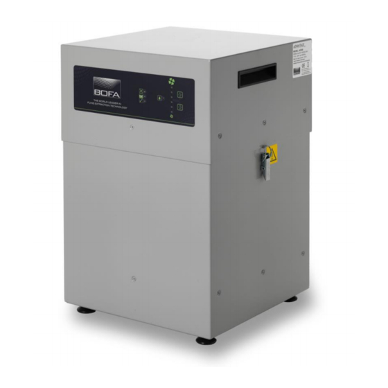
Contents Overview of your extraction system (front) Overview of your extraction system (back) Overview of the control panel Important safety notes Safety labels Unpacking and unit placement Fume capture methods Connecting to power supply Optional added features Turning extractor on / adjusting airflow Cleaning the unit Filter replacement Consumable spares &... - Page 3 Overview Control Panel Handles Clips Feet...
- Page 4 Overview Air Outlet Motor Cooling ON / OFF Switch Mains Inlet Signal Cable Inlet Air Inlet...
- Page 5 Overview...
-
Page 6: Important Safety Notes
Important Safety Instructions To reduce the risk of fire, electric shock or injury: Always isolate the system from the mains power supply before removing the pump/motor access panel. 2. Use only as described in this manual. Connect the system to a properly grounded outlet. Important safety notes Concerning symbols used on the extraction unit and referred Dangers to eyes, breathing and skin... - Page 7 Serial Number Safety Instructions For future reference, fill in your system details in the space provided. The serial number is on the rating label located on the side/rear of the unit. Serial Number: Warning and Information labels The following listing details labels used on your unit. Serial Number Label Goggles, Gloves &...
- Page 8 This unit should not be used on processes where sparks could occur, with explosive dusts and gases, or with particulates which can be pyrophoric (can spontaneously ignite), without implementation of additional precautions It is essential that nozzles or other extraction/ fume capture devices and hoses/pipework are cleaned regularly to prevent the build-up of potentially ignitable debris...
- Page 9 Before installation Packaging Removal & Unit Placement Before installation, check the extraction unit for damage. All packaging must be removed before the unit is connected to the power supply. Please read all instructions in this manual before using this extractor. Move the unit to the location where it is going to be installed and remove the outer packaging.
-
Page 10: Fume Capture Methods
Installation Enclosures The unit has been designed to remove and filter fume The extraction hose and nozzle can be attached to the containing potentially hazardous particulate and gases enclosure surrounding the marking zone provided that the generated during manufacturing processes. Such hazardous extraction point is within 50-75mm of the marking point. -
Page 11: Connecting To Power Supply
Installation Connection to Power Supply Please follow the above specification at the rear of this manual when selecting the power supply outlet for the system, ensure the power supply is suitable before connecting the system. Check the Integrity of the electrical power cable, if the supply cord is damaged the extraction unit should not be connected to the mains. -
Page 12: Optional Added Features
Voltage input or Volt free, depending on the requested Installation specification) to enable the motor within the extraction unit. Switch in “Off” position In this position the extractor motor will run without the requirement for an external start signal. This feature is useful for engineers carrying out works/ tests on the extractor without the need for the laser / auxiliary signal being present. - Page 13 Operation To set the airflow Press the Up arrow button to increase airflow and press the down arrow button to decrease airflow. The level of airflow is indicated by the vertical row of six blue LEDs to the right of the mains isolation switch. As the airflow increases, more Turning extraction unit on blue LEDs light up and the opposite for decreasing the The ON / OFF switch must be switched to the “On”...
-
Page 14: Cleaning The Unit
Maintenance Filter Information A log of filter changes should be maintained by the user. The filters require attention when the display shows the configuration shown on the next page or when the extractor no longer removes fume efficiently. It is recommended that a spare set of filters are kept on site Maintenance UK to avoid prolonged unit unavailability. -
Page 15: Filter Replacement
4. If the current pre filter is found to be serviceable Maintenance place into the new combined filter. Lower the new filter into position. Replace the motor section, and fasten the two clips. Filter Replacement If the VOC (Volatile Organic Compound) alarm option is Refer to section 2 02 for PPE requirements. - Page 16 Replacement Parts Filter disposal The combined filter is manufactured from non-toxic materials. Filters are not re-usable, cleaning used filters is not recommended. The method of disposal of the used Consumable Spares filters depends on the material deposited on them. The extraction system contains two filters. These should be For your guidance replaced when instructed to do so by the system or when the system isn’t performing (see section...
- Page 17 System Specifications Wiring schematic available upon request Spares parts list available upon request Unit: AD 350 Capacity: 380 m³/hr (223cfm) Weight: 35Kg (77.2lb) Motor: Centrifugal Fan Output: 1.1Kw Electrical supply: 115-230V Hertz: 50/60Hz Full Load Current: 12.5 A No of phases: 1 Noise Level: Below 62dB (A) (at typical operating speed) 61010 Stability test results:...
- Page 18 Contact Information BOFA Headquarters 19-20 Balena Close Creekmoor industrial Estate Poole Dorset BH17 7DU Tel. +44 (0) 1202 699 444 Email. sales@bofa.co.uk German Office Sudring 62 D-21465 Wentorf bei Hamburg Germany Tel. +49 (0) 40 739 3735-15 Email. vertrieb@bofa.co.uk BOFA Americas, Inc 303 S.Madison Street Staunton Illnois...
- Page 20 Inspection Record Local Exhaust Ventilation System - Health & Safety at Work Act 1974 - Control of Substances Hazardous to Health - Regulation 9 (2002) Thorough Examination and Testing of Local Exhaust Ventilation Systems Company: System Designation: System Installation Date: Designated Person: Inspection and Maintenance Schedules Daily checks...
- Page 21 - 1 - Process enclosure, extract offtake(s), hose/ducting and extract/filtration unit. Inspection and Maintenance Record Daily inspection Inspection of the process to ensure extract devices/nozzles/enclosures/hoses are in place and correctly positioned. Examination of the extractor to ensure it is running. This to be carried out by the operator. Daily inspection not recorded.
- Page 22 - 2 - Process enclosure, extract offtake, hose/ducting and extract/filtration unit. Inspection and Maintenance Record 2. Weekly Inspection ..Continued Weekly inspection by supervisor of physical condition of extract devices/nozzles/enclosures/hoses and extraction unit for damage, change (parts added or removed) and correct operation etc. Check also that daily inspections have been completed.
- Page 23 - 3 - Process enclosure, extract offtake, hose/ducting and extract/filtration unit. Inspection and Maintenance Record 3. Monthly Inspection In addition to weekly checks. Disconnect hoses and check for blockage and smooth operation of fan, signs of dust or vapour / gas / odour carry over. Tick boxes to confirm system ok / change. Add details of any changes.
Need help?
Do you have a question about the BOFA AD 350 and is the answer not in the manual?
Questions and answers
All 3 status lights are blinking
When all 3 status lights are blinking on a Donaldson BOFA AD 350, it indicates a loss of vacuum inside the extraction system. This can also happen during system startup or when the system is idle and waiting for a remote start signal.
This answer is automatically generated