Table of Contents
Advertisement
Quick Links
Service Manual
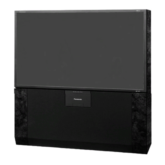
PT-65WX51E
This Simplified Service Manual is issued to add listed models to the Simplified Service Manual order No.
MTNC010522A1 (PT-47WX51E). Included in this manual are schematics that are unique to the listed models, unique
disassembly procedures, and a complete parts list for the serviceable boards are included in this Simplified Manual .
Please file and use this manual together with Simplified Service Manual, order No. MTNC010522A1 (PT-47WX51E).
"WARNING! This Service Manual is designed for experienced repair technicians only and is not designed for use by the general public.
It does not contain warnings or cautions to advise non-technical individuals of potential dangers in attempting to service a product.
Products powered by electricity should be serviced or repaired only by experienced professional technicians. Any attempt to
service or repair the product or products dealt with in this Service Manual by anyone else could result in serious injury or death."
The service technician is required to read and follow the "Safety Precautions" and "Important Safety Notice" in this Manual.
HDTV MONITOR
Simplified Manual
P5PW
Panasonic
Models
PT- 65WX51E
PT- 56WX51E
PT- 56WX51CE
Copyright 2001 by Matsushita Electric Corporation of
America. All rights reserved. Unauthorized copying
and distribution is a violation of law.
ORDER NO. MTNC010631A1
B2
Chassis
EP820
EP820
EP820
Advertisement
Chapters
Table of Contents

Related Manuals for Panasonic PT- 65WX51E


Summary of Contents for Panasonic PT- 65WX51E
- Page 1 ORDER NO. MTNC010631A1 Service Manual HDTV MONITOR Simplified Manual P5PW Panasonic Models Chassis PT- 65WX51E EP820 PT- 56WX51E EP820 PT- 56WX51CE EP820 PT-65WX51E This Simplified Service Manual is issued to add listed models to the Simplified Service Manual order No.
- Page 2 Important Safety Notice Special components are used in this projection television that are important for safety. These components are identified on the schematic diagram by the symbol and printed in BOLD TYPE on the replacement part list. It is essential that these critical parts be replaced with the manufacturer’s specified replacement part to prevent x-ray radiation, shock, fire or other hazards.
- Page 3 Important Safety Tests Measuring H.V. 4. Connect a H.V. meter (static type, class 0.1) with high voltage leads to high voltage distributor The anode caps are cemented to the CRTs. To gain on FBT. (See Fig. 4) access for high voltage measurement, remove the red CRT’s anode lead from the flyback transformer distributor.
-
Page 4: Table Of Contents
Important Safety Notice ....2 Safety Precautions ....2 General Guidelines . - Page 5 Service Notes Note: Some components may be affixed with glue. Be careful not to break or damage foil under the component or at the pins of the ICs when removing. Usually applying heat to the component for a short time while twisting with tweezers will break the component loose.
- Page 6 IMPORTANT: To protect against possible damage to as specified by government agencies and independent the solid state devices due to arcing or static testing laboratories. discharge, make certain that all ground wires and CRT To maintain original product safety design standards DAG wire are securely connected.
- Page 7 FEATURE PT-65WX51E PT-56WX51E/CE Weight (kg/lbs) 126.5/277.78 116/255.7 Power source (V/Hz) 120 / 60 Anode voltage 31.5 ± 1.0kV 75Ω, phono jack Video input jack Audio input jack 500mV RMS 47kΩ Table 1: PTV Feature Table Specifications are subject to change without notice or obligation.
- Page 8 PTV - Location of Controls PT-65WX51E POWER VOLUME CHANNEL ACTION TV/VIDEO Figure 5. Location of Controls PTV Quick Reference Control Operation Quick Reference Control Operation Power - Press to turn ON or OFF. Volume - Press to adjust Sound Level, or to adjust Audio Menus, Video Menus, and select operating features when menus are displayed.
- Page 9 Remote - Location of Controls-Basic Operation POWER Button Press to turn ON and OFF. MUTE Button Press to mute sound. A second press resumes sound. Press also to access and delete Closed Caption display. TV, VCR, DVD, CBS/CBL Component function buttons VOL (volume) Buttons Press to adjust TV sound level.
- Page 10 ISASSEMBLY FOR ERVICE PTV F 65”) RAME SSEMBLY Caution: The screen frame is painted. Handle parts with care. Follow the procedure below for the assembly of the plastic PTV screen frame. See Fig . for reference. Insert the metal support into the side and top Assemble the frame as illustrated below using pieces as shown.
- Page 11 PTV S CREENS REPARATION Caution: The PTV screens are made of thin plastic and can be broken or scratched easily, if not handled properly. Work in a clean and dust free environment to insure proper and trouble free installation. Use lint free cotton gloves while assembling the PTV screens.
- Page 12 PTV S LACEMENT OF CREENS IN CREEN RAME Place the screens in the screen frame as indicate in Fig. 8. Make sure that all supports pieces are fully engaged prior to attaching the PTV screen frame to the cabinet. Note: The screen supports are pressed into place and do not require screws.
- Page 13 RAME AND USTOMER ONTROLS ANEL NSTALLATION Note: Handle the PTV screen by holding it by its frame. Avoid scratching the delicate plastic screen. Follow the procedure below to assemble the PTV screen and control panels to the cabinet. Hold the screen assembly by its sides. Align bottom edge of the screen frame to the the sides of the PTV screen frame with the cabinet with 6 screws as illustrated in Fig .9.
- Page 14 ABINET OP AND IRROR ANEL NSTALLATION Caution: The mirror is attached to the underside of the mirror panel. Use care not to damage the mirror. Work in a dust free environment. Follow the procedure below for installation. Refer to Fig. 10 for further instructions. Attach an adhesive foam strip to the top back Carefully secure the mirror panel on the cover, as illustrated in Fig.
- Page 15 REPLACEMENT PARTS LIST Models: PT-56WX51E/CE & PT-65WX51E Important Safety Notice: Components printed in BOLD TYPE have special characteristics important for safety. When replacing any of these components use only manufacturer’s specified parts. PART NO. DESCRIPTION PART NO. DESCRIPTION C501 ECA1VM101B CAP,E 100UF-35V CAPACITORS C502...
- Page 16 REPLACEMENT PARTS LIST Models: PT-56WX51E/CE & PT-65WX51E Important Safety Notice: Components printed in BOLD TYPE have special characteristics important for safety. When replacing any of these components use only manufacturer’s specified parts. PART NO. DESCRIPTION PART NO. DESCRIPTION C704 ECKR2H391KB5 CAP,C 390PF-K-500V C897 ECQV1H474JL3...
- Page 17 REPLACEMENT PARTS LIST Models: PT-56WX51E/CE & PT-65WX51E Important Safety Notice: Components printed in BOLD TYPE have special characteristics important for safety. When replacing any of these components use only manufacturer’s specified parts. PART NO. DESCRIPTION PART NO. DESCRIPTION D312 MA188TA5 DIODE D656 MA4110MTA...
- Page 18 REPLACEMENT PARTS LIST Models: PT-56WX51E/CE & PT-65WX51E Important Safety Notice: Components printed in BOLD TYPE have special characteristics important for safety. When replacing any of these components use only manufacturer’s specified parts. PART NO. DESCRIPTION PART NO. DESCRIPTION IC870 SI-8033S INT CKT L827 TALL08T330KA...
- Page 19 REPLACEMENT PARTS LIST Models: PT-56WX51E/CE & PT-65WX51E Important Safety Notice: Components printed in BOLD TYPE have special characteristics important for safety. When replacing any of these components use only manufacturer’s specified parts. PART NO. DESCRIPTION PART NO. DESCRIPTION Q606 2SD601ARTX TRANSISTOR R306 ER0S2TKF1401...
- Page 20 REPLACEMENT PARTS LIST Models: PT-56WX51E/CE & PT-65WX51E Important Safety Notice: Components printed in BOLD TYPE have special characteristics important for safety. When replacing any of these components use only manufacturer’s specified parts. PART NO. DESCRIPTION PART NO. DESCRIPTION R380 ERDS2TJ821T RES,C 820-J-1/4W R522 ER0S2TKF7151...
- Page 21 REPLACEMENT PARTS LIST Models: PT-56WX51E/CE & PT-65WX51E Important Safety Notice: Components printed in BOLD TYPE have special characteristics important for safety. When replacing any of these components use only manufacturer’s specified parts. PART NO. DESCRIPTION PART NO. DESCRIPTION R642 ERDS2TJ101T RES,C 100-J-1/4W R904 ERDS2TJ683T...
- Page 22 SKHHDTA010 SWITCH M035 TBL2AH30041 CASTER (PIVOT) PT-65WX51E TRANSFORMERS M036 TBL2A3106 CASTER (PIVOT) PT-56WX51E/CE T501 ETH19K186AM TRANSFORMER M037 TBM2AA0012 BADGE, PANASONIC T551 KFT7AA334F1 TRANSFORMER, FLYBACK M038 TBX2AA0161G BUTTON, 7-KEY PT-56WX51E/CE T801 ETS39AG2U5BC TRANSFORMER, SWITCHING M039 TBX2AA2301GS ASSY, 7-KEY BUTTON PT-65WX51E T802...
- Page 23 REPLACEMENT PARTS LIST Models: PT-56WX51E/CE & PT-65WX51E Important Safety Notice: Components printed in BOLD TYPE have special characteristics important for safety. When replacing any of these components use only manufacturer’s specified parts. PART NO. DESCRIPTION FRAME, SCREEN TOP M058 TKE2AA00610S PT-65WX51E FRAME, SCREEN BOTTOM M059...
- Page 24 PARTS LIST ABBREVIATIONS GUIDE RESISTOR TYPE TOLERANCE Carbon ± 1% Fuse ± 5% Metal Oxide ± 10% Solid ± 20% Wire Wound ± 2% RES, C 270-J-1/4 CAPACITOR TYPE TOLERANCE Ceramic ± 0.25pF Electrolytic ± 0.5pF Polyester ± 1pF Styrol ±...
- Page 25 G-Board & K-Board Schematics G-Board Schematic K-Board Schematic - 25 - Service Manual...
- Page 26 G-Board & K-Board PCB G-Board PCB K-Board PCB - 26 - Service Manual...
- Page 27 Notes: - 27 -...
- Page 28 ® Printed in USA K01062205PL0627 - 28 -...
- Page 29 ORDER NO. MTNC010522A1 Service Manual HDTV MONITOR Simplified Manual P5PW Panasonic Models Chassis PT- 47WX49E DP820 PT- 47WX51E DP820 PT- 47WX51CE DP820 This Simplified Service Manual is issued to add listed model to the Main Service Manual order No. MTNC010417C1 (PT-51HX41E).
-
Page 30: Important Safety Notice
Important Safety Notice Special components are used in this projection television that are important for safety. These components are identified on the schematic diagram by the symbol and printed in BOLD TYPE on the replacement part list. It is essential that these critical parts be replaced with the manufacturer’s specified replacement part to prevent x-ray radiation, shock, fire or other hazards. -
Page 31: Important Safety Tests
Important Safety Tests Measuring H.V. 4. Connect a H.V. meter (static type, class 0.1) with high voltage leads to high voltage distributor The anode caps are cemented to the CRTs. To gain on FBT. (See Fig. 4) access for high voltage measurement, remove the red CRT’s anode lead from the flyback transformer distributor. - Page 32 Important Safety Notice ....2 Remote - Location of Controls ... . . 9 Safety Precautions .
-
Page 33: Leadless Chip Component (Surface Mount)
Service Notes Note: Some components may be affixed with glue. Be careful not to break or damage foil under the component or at the pins of the ICs when removing. Usually applying heat to the component for a short time while twisting with tweezers will break the component loose. -
Page 34: Feature Table
IMPORTANT: To protect against possible damage to as specified by government agencies and independent the solid state devices due to arcing or static testing laboratories. discharge, make certain that all ground wires and CRT To maintain original product safety design standards DAG wire are securely connected. -
Page 35: Pcbs Designation
FEATURE PT-47WX49E PT-47WX51E/CE Component Input Audio Out (FAO & VAO) Dolby Center Channel In Dimensions 1111 x 626 x 1236 (WxDxH) 43.7 x 24.6 x 48.7 Weight (kg/lbs) 80.5 / 177.5 82 / 180.8 Power source (V/Hz) 120 / 60 Anode voltage 31.5 ±... -
Page 36: Ptv - Location Of Controls
PTV - Location of Controls POWER VOLUME CHANNEL ACTION TV/VIDEO Figure 5. Location of Controls PTV Quick Reference Control Operation Quick Reference Control Operation Power - Press to turn ON or OFF. Volume - Press to adjust Sound Level, or to adjust Audio Menus, Video Menus, and select operating features when menus are displayed. -
Page 37: Remote - Location Of Controls Basic Operation
Remote - Location of Controls-Basic Operation Where applies POWER Button Press to turn ON and OFF. MUTE Button Press to mute sound. A second press resumes sound. Press also to access and delete Closed Caption display. TV, VCR, DVD, CBS/CBL Component function buttons VOL (volume) Buttons Press to adjust TV sound level. -
Page 38: Disassembly For Service
Disassembly for Service Note: Board ground wires may have to be disconnected to disassemble some boards. All ground wires must be reconnected using jumper leads, if necessary, before power is applied to PTV for service. Speaker Grille Removal (Fig. 7) The Speaker Grille is secured to the cabinet of the PTV. -
Page 39: Screen Frame
Screen Frame Removal 1. Remove the Speaker Grille. Disconnect the cables leading to the Keyboard and the AV Panels and remove the Keyboard and AV panel assembly. The assembly is secured by three (3) screws. Main Chassis Block 2. At this point the front cover is held only by four screws, be careful not to push the cabinet forward. - Page 40 Disassembly for CRT Replacement To facilitate CRT replacement, the complete CRT mounting chassis does not need to be removed. 1. Remove the main chassis block from the cabinet. See Fig. 11. 2. Remove the Optical bracket metal cover (rear side) by removing (6) screws from back, (2) screws from top, and (2) screws from each side.
- Page 41 8. Assemble CRT focus lens assembly to new CRT with (4) screws. Make sure focus lens adjustment Optical Bracket (Front) nut is in the same location as on other CRT focus lens. RED CRT GREEN CRT BLUE CRT Figure 18. Wire Guide. Figure 19.
- Page 42 PTV Screen Assemblies Protective Screen FRONT Label on lower left corner (front side) Labels on opposite sides Front Cabinet Label on Lenticular Screen lower left corner (note vertical ridges) (rear side) Fresnel Screen REAR (note circular ridges) Figure 21. Screen Assemblies. Dynamic Focus Adjustments Procedure: 1.
- Page 43 2. Adjust SBPOS to obtain the same size on both borders (to certer the image). Convergence Alignment Template Note: A convergence alignment template, part number TXFQD01ESER for 47”, is available through Matsushita/Panasonic Services Grid Dimensions: 47” Models: 1036mm Horizontal X 584mm Vertical. - 15 - Service Manual...
- Page 44 REPLACEMENT PARTS LIST Models: PT-47WX49E, PT-47WX51E & PT-47WX51CE Important Safety Notice: Components printed in BOLD TYPE have special characteristics important for safety. When replacing any of these components use only manufacturer’s specified parts. REF NO. PART NO. DESCRIPTION REF NO. PART NO.
- Page 45 REPLACEMENT PARTS LIST Models: PT-47WX49E, PT-47WX51E & PT-47WX51CE Important Safety Notice: Components printed in BOLD TYPE have special characteristics important for safety. When replacing any of these components use only manufacturer’s specified parts. REF NO. PART NO. DESCRIPTION REF NO. PART NO.
- Page 46 REPLACEMENT PARTS LIST Models: PT-47WX49E, PT-47WX51E & PT-47WX51CE Important Safety Notice: Components printed in BOLD TYPE have special characteristics important for safety. When replacing any of these components use only manufacturer’s specified parts. REF NO. PART NO. DESCRIPTION REF NO. PART NO.
- Page 47 REPLACEMENT PARTS LIST Models: PT-47WX49E, PT-47WX51E & PT-47WX51CE Important Safety Notice: Components printed in BOLD TYPE have special characteristics important for safety. When replacing any of these components use only manufacturer’s specified parts. REF NO. PART NO. DESCRIPTION REF NO. PART NO.
- Page 48 REPLACEMENT PARTS LIST Models: PT-47WX49E, PT-47WX51E & PT-47WX51CE Important Safety Notice: Components printed in BOLD TYPE have special characteristics important for safety. When replacing any of these components use only manufacturer’s specified parts. REF NO. PART NO. DESCRIPTION REF NO. PART NO.
- Page 49 REPLACEMENT PARTS LIST Models: PT-47WX49E, PT-47WX51E & PT-47WX51CE Important Safety Notice: Components printed in BOLD TYPE have special characteristics important for safety. When replacing any of these components use only manufacturer’s specified parts. REF NO. PART NO. DESCRIPTION REF NO. PART NO.
- Page 50 REPLACEMENT PARTS LIST Models: PT-47WX49E, PT-47WX51E & PT-47WX51CE Important Safety Notice: Components printed in BOLD TYPE have special characteristics important for safety. When replacing any of these components use only manufacturer’s specified parts. REF NO. PART NO. DESCRIPTION REF NO. PART NO.
- Page 51 OTHERS M030 TBL2AH30031 CASTER, STATIONARY TNR001 ENG36602G TUNER M031 TBL2A3106 CASTER, PIVOT TNR002 ENG36603G TUNER M032 TBM2AA0012 BADGE, PANASONIC M001 EUR511517 REMOTE CONTROL PT-47WX49E M033 TBX2AA0161G BUTTON, 7-KEY REMOTE CONTROL M002 EUR7603Z40 PT-47WX51E/CE M034 TKP2AA0681 LED PANEL BATTERY COVER, REMOTE CONTROL...
- Page 52 Schematic Notes IMPORTANT SAFETY NOTICE CHIP TRANSISTOR THIS SCHEMATIC DIAGRAM INCORPORATES SPECIAL LEAD DESIGNATION FEATURES THAT ARE IMPORTANT FOR PROTECTION FROM X-RADIATION, FIRE AND ELECTRICAL SHOCK HAZARDS. WHEN SERVICING ESSENTIAL THAT ONLY MANUFACTURERS SPECIFIED PARTS BE USED FOR THE CRITICAL COMPONENTS DESIGNATED WITH A IN THE SCHEMATIC.
- Page 53 Schematic Notes NOTA DE SEGURIDAD DIAGRAMAS ELÉCTRICOS INCLUYEN CARACTERÍSTICAS ESPECIALES MUY IMPORTANTES IDENTIFICACIÓN DE TERMINALES PARA TRANSISTORES EN CHIP PARA PROTECCIÓN CONTRA RAYOS-X, QUEMADURAS Y DESCARGAS ELÉCTRICAS. CUANDO SERVICIO IMPORTANTE USAR PARA REEMPLAZO COMPONENTES CRITICOS, SOLO PARTES ESPECIFICADAS POR EL FABRICANTES. LOS COMPONENTES CRITICOS ESTAN SEÑALADOS EN LOS DIAGRAMAS POR EL SIMBOLO NOTAS DE LOS DIAGRAMAS...
- Page 54 Schematic Notes 1. RESISTOR Unit of resistance is ohm (Ω), (K=1,000, M=1,000,000) Non Flammable Solid Metal Oxide Metal (Precision and high stability) Wire Wound Thermistor Fusible Positive coefficient Thermistor Flame Proof Rectangular 2. CAPACITOR Unit of capacitance is µF, unless otherwise noted. Electrolytic Metallized Polyester Tantalum...
- Page 55 G & K-BOARD SCHEMATICS & LAYOUTS -- DIAGRAMAS ELÉCTRICOS Y CIRCUITOS IMPRESOS DE LAS TARJETAS G , K G & K-BOARDS -- TARJETAS G , K CHIP TRANSISTOR LEAD DESIGNATION Note • The board layouts were modified to enhance and display traces otherwise hidden by a mask.
- Page 56 A-BOARD -- TARJETA-A A-BOARD SCHEMATIC -- DIAGRAMA ELÉCTRICO TARJETA-A - 28 -...
- Page 57 A-BOARD SCHEMATIC -- DIAGRAMA ELÉCTRICO TARJETA-A A-BOARD -- TARJETA-A - 29 -...
- Page 58 A-BOARD - TARJETA-A A-BOARD SCHEMATIC -- DIAGRAMA ELÉCTRICO TARJETA-A - 30 -...
- Page 59 A-BOARD SCHEMATIC -- DIAGRAMA ELÉCTRICO TARJETA-A A-BOARD -- TARJETA-A - 31 -...
- Page 60 A-BOARD - TARJETA-A A-BOARD VOLTAGES -- VOLTAJES TARJETA-A A-Board Voltage Measurements (Integrated Circuits) IC7001 IC7002 IC2302 ..0.00 ..0.00 ..-22.21 ..-20.95 ..0.00 .
- Page 61 Notes: - 33 -...
- Page 62 ® Printed in USA K01052203ZR0511 - 34 -...
- Page 63 ORDER NO. MTNC010417C1 Service Manual HDTV MONITOR Main Manual (P5P) Panasonic Models Chassis PT-51HX41E AP820 PT-51HX41CE AP820 PT-56HX41E AP820 PT-56HX41CE AP820 PT-61HX41E AP820 PT-61HX41CE AP820 This Service manual is issued as a service guide for the models of the P5P family listed above. Included in this manual are a set of schematics, alignment procedures, disassembly procedures and a complete parts list.
- Page 64 Important Safety Notice Special components are used in this projection television which are important for safety. These components are identified on the schematic diagram by the symbol and printed in BOLD TYPE on the replacement part list. It is essential that these critical parts are replaced with the manufacturer’s specified replacement part to prevent x-ray radiation, shock, fire or other hazards.
- Page 65 Important Safety Tests Measuring H.V. 4. Connect a H.V. meter (static type, class 0.1) with high voltage leads to high voltage distributor The anode caps are cemented to the CRTs. To gain on FBT. (See Figure 4) access for high voltage measurement, remove the red CRT’s anode lead from the flyback transformer distributor.
- Page 66 Important Safety Notice ....2 Serviceman Mode (Electronic Controls) ..25 Quick Entry to Serviceman Mode: ..25 Safety Precautions .
-
Page 67: Service Notes
Service Notes Note: These components are affixed with glue. Be careful not to break or damage any foil under the component or at the pins of the ICs when removing. Usually applying heat to the component for a short time while twisting with tweezers will break the component loose. Leadless Chip Component How to Replace Flat-IC (surface mount) -
Page 68: Feature Table
Service Notes (Continued) IMPORTANT: To protect against possible damage to as specified by government agencies and independent the solid state devices due to arcing or static testing laboratories. discharge, make certain that all ground wires and CRT To maintain original product safety design standards DAG wire are securely connected. -
Page 69: Boards Designation
Boards Designation BOARD PART NUMBER BOARD DESCRIPTION G-BOARD TNP2AA088 FRONT A/V INPUTS K-BOARD TNP2AA087 KEYBOARD R-BOARD TNPA0615AB IR SENSOR LR-BOARD TNPA1810 RED DRIVER LG-BOARD TNPA1811 GREEN DRIVER LB-BOARD TNPA1812 BLUE DRIVER MAIN CHASSIS, VIDEO PROCESSING, A-BOARD TNPH0370 CONVERGENCE, AUDIO PROCESSING PIP PROCESSING, SPLIT, SEARCH, DH-BOARD TNPA2033... -
Page 70: Ptv - Location Of Controls
PTV - Location of Controls POWER VOLUME CHANNEL ACTION TV/VIDEO Figure 5. Location of Controls PTV Quick Reference Control Operation Quick Reference Control Operation Power - Press to turn ON or OFF. Volume - Press to adjust Sound Level, or to adjust Audio Menus, Video Menus, and select operating features when menus are displayed Channel - Press to select programmed channels. -
Page 71: Remote - Location Of Controls
Remote - Location of Controls POWER Button Press to turn ON and OFF. MUTE Button Press to mute sound. A second press resumes sound. Press also to access and delete Closed Caption display. TV, VCR, DVD, CBS/CBL Component function buttons VOL (volume) Buttons Press to adjust TV sound level. -
Page 72: Chassis & Boards Layout
Chassis & Boards Layout Front Corner View Back View Figure 7. Chassis & Boards Layout. Board Description Main Chassis, Video Processing, Convergence, Blue CRT Output Audio Processing Green CRT Output Power Supply, Vertical Out, Horizontal Out Red CRT Output PIP Processing, Split, Search, Formats IR Sensor - 10 - Service Manual... -
Page 73: Disassembly For Service
Disassembly for Service Note: Board ground wires may have to be disconnected to disassemble some boards. All ground wires must be reconnected using jumper leads, if necessary, before power is applied to PTV for service. Speaker Grille Removal 2. Remove (3) screws from around the A/V terminal board (marked with arrows). -
Page 74: Cabinet Front Removal
Disassembly for Service (Continued) Cabinet Front Removal 4. Note exact orientation of each screen. The orientation and order of the screens is critical for (Figure 11) projecting pictures properly. Detailed screen 1. First remove the Speaker Grill and the center assembly can be seen in Figur e20. -
Page 75: Disassembly For Crt Replacement
Disassembly for Service (Continued) Disassembly for CRT Replacement X-RAYS SHIELD To facilitate CRT replacement, the complete CRT 10. To insure X-Rays radiation protection, the lens mounting chassis does not need to be removed. must be mounted in place at all times when power 1. -
Page 76: Optical Block Position Adjustment
5. Wire the anode lead wire. 7. Press yoke against bell of CRT and tighten the clamp just snug enough so it will not easily shift. 8. Assemble CRT focus lens assembly to new CRT Optical Bracket (Front) with (4) screws. Make sure focus lens adjustment nut is in the same location as on other CRT focus lens. -
Page 77: Ptv Screen Assemblies
PTV Screen Assemblies Protective Screen FRONT Label on lower left corner (front side) Labels on opposite sides Front Cabinet Label on Lenticular Screen lower left corner (note vertical ridges) (rear side) Fresnel Screen REAR (note circular ridges) Figure 20. Screen Assemblies. B+ Voltages Table Preparation: Set the following controls... -
Page 78: Crt Set Up
CRT Set Up CAUTION: Insure yoke plugs on the A-Board Procedure: are reconnected before turning the PTV 1. Enter to Service mode and set the following default ON to prevent damage to the horizontal DATA: output transistor and/or CRTs. • H-PAR to +263 1. -
Page 79: Focus - Optical Lens Adjustment
3. Adjust red lens focus (mechanical) until focus is 4. Position the longer tab of the four-pole magnet to best. degrees (uncorrected position). (See 4. Adjust red focus VR again. Figure 27). 5. Repeat for blue focus VR while projecting blue only. -
Page 80: Vertical Size Adjustment (Vsize)
9. If the position of the dots moved after repeated 6. Remove lens covers enable digital adjustments, adjust until the movement of the dots convergence by changing DAC MUTE from 1 to 0. is minimized. 10. Turn the red focus VR fully clockwise. 11. -
Page 81: Pincushion Adjustment (Pcc)
Pincushion Adjustment (PCC) 9. Transfer lens cover from blue to red, so that blue is projected. Procedure: 10. Adjust blue deflection coil until the horizontal 1. Cover Red and Blue Lenses. center line matches the pattern of the grid and is 2. -
Page 82: Coarse Adjustment Mode (Coarse)
Raster Setup: “COARSE ADJ MODE” options press “TV/VIDEO” 1. Enter to service mode (red CHK). on remote again for 3 seconds. 2. In SET-UP (Roller Guide menu) 18. In “FINE ADJUSTMENT MODE” options, press CONVERGENCE 1 set all values to 0. “MUTE”... - Page 83 5. Press “7” then “ACTION” key on remote to save 18. Press “7” then “ACTION” key on remote to save changes. changes 6. Enter to linearity “G-LINEAR” mode by pressing “TV/VIDEO”. 7. Adjust linearity by pressing VOL right-left until A=B (See Figure 39) Figure 42.
-
Page 84: Fine Adjustment Mode (Fine)
25. Enter LINEARITY “R-LINEAR” mode Fine Adjustment Mode (FINE) pressing TV/VIDEO. (Convergence) 26. Adjust Horizontal linearity (See Figure 39) Note: It is strongly recommended to first read and 27. Enter to SIZE “R-SIZE” mode by pressing TV/ understand the following section prior to VIDEO make any adjustment. - Page 85 7. This mode afects a wide area around the cursor 17. Begin adjustment from the center to the edge of than other adjustment modes, See values on the screen. screen pressing RECALL remote left/right (seeFigure 47) 8. Begin adjustment from the center to the edge of the screen.
-
Page 86: Horizontal And Vertical Size Check
TXFQD03ESER for 56” & 61”, is available ensure the proper size and shape of the alignment through Matsushita/Panasonic Services. rasters. It is 6 blocks across by 6 blocks high. The grid dimensions vary with the mode of operation. -
Page 87: Serviceman Mode (Electronic Controls)
16:9 & 4:3”), a 480i, 480p, 1080i test quick guide. pattern obtained from Panasonic TU-DST51A (Set-top box). Quick Entry to Serviceman Mode: When minor adjustments need to be done to the Exiting the Serviceman Mode: electronic controls, the method of Entering the... - Page 88 Service Mode (Electronic Controls, Continued) a. Press Note: Registers marked as FIXED are factory preset, buttons on the Remote Control to select any of the default value must not be changed the seven Service Sub Adjustment Addresses. (“a” in Figure 54) b.
- Page 89 a. Press Note: Registers marked as FIXED are factory preset, buttons on the Remote Control to select any of the default value must not be changed the seven Service Sub Adjustment Addresses. (“a” in Figure 54) b. Press Important Note: Write down the original values (“b”...
-
Page 90: Instructional Flow Chart For Serviceman Mode
Instructional Flow Chart for Serviceman Mode NORMAL MODE ENTRY TO SERVICEMAN MODE AGING MODE • Select CABLE Mode. • Press VOL UP and ACTION simultaneously on PTV • Set SLEEP time for 30 Min. • Yellow “CHK” appears in upper left corner of screen. •... - Page 91 Instructional Flow Chart for Serviceman Mode - Continued ON REMOTE CONTROL TO (previous/next adjustment ON REMOTE TO VOL VOL to make adjustment Press POWER or ACTION to exit the POWER adjustment. (ON REMOTE) EXIT Press POWER to exit DACs MENU then press ACTION POWER simultaneously for at least 2 seconds to exit...
-
Page 92: Hv_Feedback Voltage
HV_Feedback Voltage Tint Adjustment (TINT) Procedure: This adjustment should be performed 1. Apply a NTSC all black pattern. Preparation: 5. Set the following in the user picture menu as 2. Connect meter (+) to TPD33 and (-) to TPGND1 follows: 3. -
Page 93: Red, Green & Blue Screen Cutoff
Service Mode (Electronic Controls, Continued) Red, Green & Blue Screen Cutoff MTS Circuit Adjustments 1. Use either a no input signal condition or raster from Note: It is important to adjust the MTS circuit in the the NTSC generator. order shown below. 2. -
Page 94: Clock Adjustment (Clock)
Service Mode (Electronic Controls, Continued) Note: Set the 30% modulation with the P.L and N.R. switches OFF then turn them ON while testing. 5. Adjust MTS High-Level Separation (SEPAH) data until the amplitude of the waveform measured on the scope is minimum. 6. -
Page 95: Audio Signal Path Block Diagram
Audio Signal Path Block Diagram Figure 61. Audio Signal Path Block Diagram - 33 - Service Manual... -
Page 96: Video-Chroma Signal Path Block Diagram
Video-Chroma Signal Path Block Diagram Figure 62. Video-Chroma Signal Path Block Diagram. - 34 - Service Manual... -
Page 97: Iic Connection
IIC Connection A-Board IC1002 IC2451 IC7107 IC2201 AUDIO CONTROL CONVERGENCE IC1004 EEPROM IC3001 TUNER1 IC3002 TUNER2 A/V SELECTOR MAIN A/V SELECTOR IC2505 IC4504 IC4513 IIC2 MAIN GC1 SUB GC1 DH-Board IC9901 IC9906 AMDP1+ D-Board IC601 IC602 Figure 63. IIC Connection - 35 - Service Manual... -
Page 98: Description Of Connectors
Description of Connectors LG2---D5 LG4---LB1 A51---R 210V 210V STB 3.3V RM_IN HEATER 6.3V OFF MUTE +20V +12V A1---D1 HEATER +18V S-ABL 140V +18V -18V 140V LG1---A15 -18V C_BTL 40V A12---CY_G AC ON/OFF P_BTL 40V GH-R STBY 7V GV-R A11---CY_R S-ABL +12V RH-R A2---D2... - Page 99 Description of Connectors (continued) A3---D3 V-PULSE H-PULSE SET +5V A6---G1 A4---D4 HHS DET +18V +18V -18V -18V DFCUT - 37 - Service Manual...
- Page 100 REPLACEMENT PARTS LIST Models: PT-51HX41E/CE, PT-56HX41E/CE & PT-61HX41E/CE Important Safety Notice: Components printed in BOLD TYPE have special characteristics important for safety. When replacing any of these components use only manufacturer’s specified parts. REF NO. PART NO. DESCRIPTION REF NO. PART NO.
- Page 101 REPLACEMENT PARTS LIST Models: PT-51HX41E/CE, PT-56HX41E/CE & PT-61HX41E/CE Important Safety Notice: Components printed in BOLD TYPE have special characteristics important for safety. When replacing any of these components use only manufacturer’s specified parts. REF NO. PART NO. DESCRIPTION REF NO. PART NO.
- Page 102 REPLACEMENT PARTS LIST Models: PT-51HX41E/CE, PT-56HX41E/CE & PT-61HX41E/CE Important Safety Notice: Components printed in BOLD TYPE have special characteristics important for safety. When replacing any of these components use only manufacturer’s specified parts. REF NO. PART NO. DESCRIPTION REF NO. PART NO.
- Page 103 REPLACEMENT PARTS LIST Models: PT-51HX41E/CE, PT-56HX41E/CE & PT-61HX41E/CE Important Safety Notice: Components printed in BOLD TYPE have special characteristics important for safety. When replacing any of these components use only manufacturer’s specified parts. REF NO. PART NO. DESCRIPTION REF NO. PART NO.
- Page 104 REPLACEMENT PARTS LIST Models: PT-51HX41E/CE, PT-56HX41E/CE & PT-61HX41E/CE Important Safety Notice: Components printed in BOLD TYPE have special characteristics important for safety. When replacing any of these components use only manufacturer’s specified parts. REF NO. PART NO. DESCRIPTION REF NO. PART NO.
- Page 105 REPLACEMENT PARTS LIST Models: PT-51HX41E/CE, PT-56HX41E/CE & PT-61HX41E/CE Important Safety Notice: Components printed in BOLD TYPE have special characteristics important for safety. When replacing any of these components use only manufacturer’s specified parts. REF NO. PART NO. DESCRIPTION REF NO. PART NO.
- Page 106 REPLACEMENT PARTS LIST Models: PT-51HX41E/CE, PT-56HX41E/CE & PT-61HX41E/CE Important Safety Notice: Components printed in BOLD TYPE have special characteristics important for safety. When replacing any of these components use only manufacturer’s specified parts. REF NO. PART NO. DESCRIPTION REF NO. PART NO.
- Page 107 REPLACEMENT PARTS LIST Models: PT-51HX41E/CE, PT-56HX41E/CE & PT-61HX41E/CE Important Safety Notice: Components printed in BOLD TYPE have special characteristics important for safety. When replacing any of these components use only manufacturer’s specified parts. REF NO. PART NO. DESCRIPTION REF NO. PART NO.
- Page 108 TJB2A10012 TERMINAL, A/V (FRONT) M060 TBL2AH30031 CASTER (STATIONARITY) M061 TBL2A3106 CASTER (PIVOT) M062 TEKX008 DOOR CATCH M063 TBM2AA0012 BADGE, PANASONIC M064 TBX2AA2401S ASSY, 7-KEY BUTTON M065 TQB2AA7076 V-CHIP ROLLER GUIDE MANUAL, OWNERS M066 TQB2AA0381 PT-51HX41E, PT-56HX41E PT-61HX41E MANUAL, OWNERS M067...
-
Page 109: Parts List
REPLACEMENT PARTS LIST DESCRIPTION OF ABBREVIATIONS GUIDE RESISTOR TYPE TOLERANCE Carbon +/- 1% Fuse +/- 5% Metal Oxide +/- 10% Solid +/- 20% Wire Wound +/- 2% RES, C 270-J-1/4 CAPACITOR TYPE TOLERANCE Ceramic +/- 0.25pF Electrolytic +/- 0.5pF Polyester +/- 1pF Styrol +/- 5%... - Page 110 SCHEMATIC NOTES: 1. RESISTOR All resistors are carbon 1/4W resistor, unless otherwise noted by the following marks. Unit of resistance is ohm (Ω), (K=1,000, M=1,000,000) Non Flammable Solid Metal Oxide Metal (Precision and high stability) Wire Wound Thermistor Fusible Positive coefficient Thermistor Flame Proof Rectangular 2.
-
Page 111: D-Board Layout
D-Board Layout ALL MODELS - 49 -... - Page 112 ALL MODELS D-Board Schematic, Left Portion - 50 -...
- Page 113 D-Board Schematic, Right Portion ALL MODELS - 51 -...
- Page 114 ALL MODELS A-Board Schematic, Left Portion - 52 -...
- Page 115 A-Board Schematic, Left Middle Portion ALL MODELS - 53 -...
- Page 116 ALL MODELS A-Board Schematic, Right Middle Portion - 54 -...
- Page 117 A- Board Schematic, Right Portion ALL MODELS - 55 -...
-
Page 118: Dh-Board Schematic
ALL MODELS DH-Board Schematic - 56 -... -
Page 119: K, G & R-Board Schematics & Layouts
K, G & R Board Schematics & Layouts ALL MODELS G-Board Schematic R-Board Schematiematic K-Board Schematic R-Board Layout K-Board Layout G-Board Layout - 57 -... - Page 120 ALL MODELS LR-Board Layout & Schematic LR-Board Voltage Measurements (Transistors) Q355 Q309 Q354 Q353 Q308 Q302 175.30 176.40 11.50 177.00 8.10 2.90 0.30 8.10 175.70 216.80 1.70 11.50 176.20 176.40 11.90 176.80 8.00 2.50 Q301 Q303 Q901 Q957 Q904 Q958 0.00 0.60 137.90...
-
Page 121: Lb-Board Schematic, Layout & Voltages
LB-Board Schematic, Layout & Voltages ALL MODELS LB-Board Voltage Measurements (Transistors) Q395 Q370 Q393 Q394 Q367 Q361 173.00 174.10 174.40 11.90 8.10 7.90 0.30 8.20 216.90 173.10 2.50 0.00 174.00 174.00 174.20 11.50 8.20 8.10 Q364 Q362 Q961 Q959 Q964 Q960 6.80 7.50... -
Page 122: Lg-Board Schematic, Layout & Voltages
ALL MODELS LG-Board Schematic, Layout & Voltages LG-Board Voltage Measurements (IC & Transistors) Q331 Q334 Q375 Q338 Q374 Q373 2.89 8.14 175.90 175.20 11.90 176.50 11.51 1.43 8.20 0.30 175.20 216.80 2.47 8.00 175.90 175.80 11.50 176.00 IC880 Q956 Q941 Q955 Q935 Q936... - Page 123 Voltages ALL MODELS A-Board Voltage Measurements (IC’s) D-Board Voltage Measurements (IC & Transistors) IC2302 IC7001 IC7002 IC2302 IC701 IC602 IC603 ..-22.21 ..-20.95 ..0.00 ..0.00 .
-
Page 124: Waveforms
ALL MODELS WAVEFORMS D-Board A-Board 1.50KV p-p 14.0V p-p 68.8V p-p 36.0V p-p 4.00V p-p 5.36V p-p 6.56V p-p 6.72V p-p Q551-C Q551-B IC451 PIN 5 (V-OUT) IC451 PIN 3 A15 PIN 9 (VM OUT) A15 PIN 6 (GREEN OUT) A15 PIN 4 (RED OUT) A15 PIN 2 (BLUE OUT) 8.40V p-p... - Page 125 Notes: - 63 -...
- Page 126 ® Printed in USA K01052205PL0518 - 64 -...
Need help?
Do you have a question about the PT- 65WX51E and is the answer not in the manual?
Questions and answers