Table of Contents
Advertisement
Für Erlauterungen in Deutsch, konsultieren Sie bitte die mitgelieferte CD-ROM.
DEUTSCH
(Zurück Decke)
Pour des explications en français, veuillez vous reporter au CD-ROM fourni.
FRANÇAIS
(Quatrième de couverture)
Per le istruzioni in italiano, vedere il CD-ROM in dotazione. (Retro della copertina)
ITALIANO
Para la explicación en español, consulte el CD-ROM suministrado. (Cubierta trasera)
ESPAÑOL
This manual is also contained as a PDF file on the CD-ROM supplied with the unit. (Back cover)
Before operating this product, please read the instructions carefully and save this manual for future use.
SS0812KT0 -PS
Printed in Japan
Operating Instructions
BT-LH2170P
Model No.
BT-LH2170E
Model No.
LCD Video Monitor
ENGLISH
VQT4M18
Advertisement
Table of Contents

Related Manuals for Panasonic BT-LH2170


Summary of Contents for Panasonic BT-LH2170
-
Page 1: Operating Instructions
Operating Instructions LCD Video Monitor BT-LH2170P Model No. BT-LH2170E Model No. Für Erlauterungen in Deutsch, konsultieren Sie bitte die mitgelieferte CD-ROM. DEUTSCH (Zurück Decke) Pour des explications en français, veuillez vous reporter au CD-ROM fourni. FRANÇAIS (Quatrième de couverture) Per le istruzioni in italiano, vedere il CD-ROM in dotazione. (Retro della copertina) ITALIANO Para la explicación en español, consulte el CD-ROM suministrado. -
Page 2: Read This First ! (For Bt-Lh2170P)
Wrongly wired extension cords are a major This Monitor is for use only with Panasonic Wall Mount cause of fatalities. The fact that the equipment operates Adaptor, BT-WMA17G. Use with other Wall Mount or Rack... -
Page 3: Important Safety Instructions
Read this first ! (for BT-LH2170P) (continued) FCC NOTICE (USA) This device complies with part 15 of the FCC Rules. Operation is subject to the following two conditions: (1) This device may not cause harmful interference, and (2) this device must accept any interference received, including interference that may cause undesired operation CAUTION: This equipment has been tested and found to comply with the limits for a class A digital device, pursuant to Part 15 of the... -
Page 4: Read This First ! (For Bt-Lh2170E)
[ India Only ] For the purpose of recycling to facilitate effective utilization of resources, please return this product to a nearby authorized collection center, registered dismantler or recycler, or Panasonic service center when disposing of this product. Please see the Panasonic website for further information on collection centers, etc. - Page 5 If you lose the fuse cover the plug must not be used until a replacement cover is obtained. A replacement fuse cover can be purchased from your local Panasonic Dealer. Fuse indicates safety information. Note regarding the Power Management function specified under COMMISSION REGULATION (EC) No 1275/2008 implementing Directive 2009/125/EC of the European Parliament and of the Council.
- Page 6 Read this first ! (for BT-LH2170E) (continued) EMC NOTICE FOR THE PURCHASER/USER OF THE APPARATUS 1. Applicable standards and operating environment The apparatus is compliant with: • standards EN55103-1 and EN55103-2 2009, and • electromagnetic environments E1, E2, E3 and E4. 2.
-
Page 7: Transportation Precautions
Transportation precautions Do not try to lift the monitor by grabbing the LCD panel. Do not place the monitor face down during transportation to prevent damaging it. Keep it upright. Do not expose the LCD panel to strong pressure or pressure from pointed objects. Take care especially during transportation. Exposing the LCD panel to strong pressure may result in blurring or other damage. -
Page 8: Table Of Contents
Table of Contents Read this first ! (for BT-LH2170P) ...........2 Loading user data ..............22 Read this first ! (for BT-LH2170E) ...........4 Main Menu ................23 Menu configuration ..............23 Transportation precautions .............7 2D/3D ASSIST ..............24 About this instruction manual ..........7 MARKER ................24 Precautions for Use..............7 MARKER types ..............26 VIDEO CONFIG ..............27... -
Page 9: Standard Accessories · Optional Units
Standard accessories · Optional units „ Standard accessories „ Power cable x 1 (BT-LH2170P) Power cable x 2 (BT-LH2170E) Stand (already attached to the product) x 1 Stand screws (already attached to the product) x 3 CD-ROM x 1 Protection panel mounting screws (8 mm long M3 screws) x 4 •... -
Page 10: Dimensions
Dimensions Unit: mm (inches) 280(11) 260(10-1/4) (2-13/16) (3-15/16) 2.5(1/8) 510(20-1/16) 4-M4 P=0.7 27(1-1/16) 42.5(1-5/8) 4-M3 475.2(18-5/8) • When the unit will be permanently installed in one place, we recommend securing it in place using the screw holes at the bottom of the stand. -
Page 11: Controls And Their Functions
Controls and Their Functions Video monitor Front panel Rear panel Front panel Power Supply Rear panel (→page 12) (You can switch between AC (→page 13) and DC (→page 14)) Tally Lamp (Red and Green) Can be lit by a control signal (red tally and green tally) via GPI. -
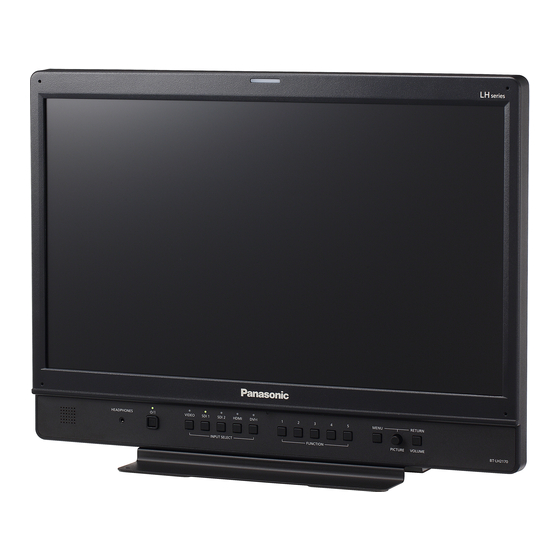
Page 12: Front Panel
Controls and Their Functions (continued) Front panel HEADPHONES SDI 1 SDI 2 HDMI DVI-I MENU RETURN VIDEO INPUT SELECT FUNCTION PICTURE VOLUME POWER <8> switch MENU button, rotary knob (with push-on switch (PIC- Switches the power supply ON/OFF. When the power is on, TURE) and RETURN/VOLUME button (→page 16) the LED (green) lights. -
Page 13: Rear Panel
Controls and Their Functions (continued) Rear panel VIDEO terminal (BNC) : This is the VIDEO signal (composite signal) input terminal. : This is the input signal through-out terminal. DVI-I RS-485 Unless a cable is connected to the VIDEO OUT terminal, the VIDEO IN terminal is automatically terminated at VIDEO 75 Ω. -
Page 14: Power Supply
Power supply Connecting the power cable Attach the power cable to the unit. „ When using external DC power (12 V DC) „ You can slide open the power cover to switch from AC input to external DC input. Power cover <Note>... -
Page 15: Detaching And Attaching The Stand
Detaching and Attaching the Stand The stand is detachable. • When detaching and attaching the stand, it is recommended that you place the monitor flat on the edge of a desk or table with a soft cloth or similar material spread underneath. •... -
Page 16: On-Screen Display
On-screen Display The screen shows the operation status display, the main menu (MAIN MENU) / FUNCTION menu / INPUT SELECT menu displays, picture adjusting (PICTURE) menu display, audio volume display, sharpness display, FUNCTION display, audio volume bar meter display, time code (TC) display, closed caption (CC) display, IMD (in monitor display) display and other information. Operating status display Signal format •... -
Page 17: Picture Adjusting (Picture) Menu Display
On-screen Display (continued) To close a menu, press <MENU>. • The menu display disappears after approx. 2 minutes of inaction. (The value shown before the display clears is confirmed.) Picture adjusting (PICTURE) menu display Press rotary knob <PICTURE> when no menu is dis- played. -
Page 18: Audio Volume Bar Meter Display
On-screen Display (continued) Audio volume bar meter display ● Normal operating mode • A color bar meter indicates the audio level for SDI, HDMI and AUDIO signals. Reference point • The display method of the audio volume bar meter can be set Channel display in the menu.(→page 45) 0 dB point... -
Page 19: Closed Caption (Cc) Display
On-screen Display (continued) Closed caption (CC) display • This unit can display closed captions with an SDI or VIDEO signal input. • Closed captions comply with the following standards. • Composite Standard EIA/CEA-608 (VBI), OP-42 Closed caption • SD-SDI CC Standard EIA/CEA-608 (ANC/VBI), OP-42 display area •... -
Page 20: How To Use The On Screen Menu
How to Use the On Screen Menu Main menu (MAIN MENU) FUNCTION menu • For details on how to open the main menu, refer to “Main • For details on how to open the [FUNCTION] menu, refer to menu (MAIN MENU)/FUNCTION menu/INPUT SELECT menu “Main menu (MAIN MENU)/FUNCTION menu/INPUT SELECT displays”... -
Page 21: Picture Adjusting (Picture) Menu
How to Use the On Screen Menu (continued) Turn the rotary knob <PICTURE> to select a set value Picture adjusting (PICTURE) menu and press the rotary knob <PICTURE>. Turn the rotary knob <PICTURE> to select a menu item • The set value is confirmed and the menu reappears. and press the rotary knob <PICTURE>. -
Page 22: User Data
User Data This monitor can save up to five combinations of set values for MAIN MENU and screen adjustments made in the [PICTURE] (picture adjusting) menu as user data that can be recalled. You can also return set values and adjustments to their factory defaults. User data include the following settings. -
Page 23: Main Menu
Main Menu Menu configuration MAIN MENU 2D/3D ASSIST MARKER MARKER 16:9 GAMMA SELECT VIDEO CONFIG FILM GAMMA BACK SYSTEM CONFIG SUB WINDOW COLOR TEMP. CENTER MENU POSITION SHARPNESS MODE USER0 to 63 CROSS STATUS DISPLAY SHARPNESS H COLOR INPUT NAME SETUP SHARPNESS V GPI MARKER1 VIDEO... -
Page 24: 2D/3D Assist
Main Menu (continued) 2D/3D ASSIST Underlined values indicate factory defaults. Setting Description Switches between 2D mode and 3D assist mode. 3D ASSIST [2D] Operates in 2D mode. [3D ASSIST] Operates in 3D assist mode. When you switch to [3D ASSIST], the input line selection will be force switched to SDI1 or SDI2. - Page 25 TYPE1 Selects conventional monitor or camera recorder marker size. TYPE2 [TYPE1] Conventional monitor marker size [TYPE2] Marker size compliant with camera recorder (Panasonic camera) CROSS HATCH Turns the cross hatch grid on and off and sets its density. [OFF] No cross hatch grid display...
-
Page 26: Marker Types
Main Menu (continued) MARKER types „ 16:9 marker „ 4:3 marker „ „ (Displayed for HD input and SD input in 16:9 ratio mode.) (Displayed for SD input in 4:3 aspect ratio mode) The marker is only displayed as a vertical bar. In addition, the This marker is displayed as a dotted line. -
Page 27: Video Config
Main Menu (continued) VIDEO CONFIG The underlined values are factory defaults. Submenu Setting Description GAMMA SELECT STANDARD Selects gamma curve. FILM [STANDARD] Standard mode (power of 2.2) STDIO/PST [FILM] Film mode CINEMA [STDIO/PST] Color emphasis mode (power of 2.35) [CINEMA] CINEMA mode (power of 2.6) •... - Page 28 Main Menu (continued) Submenu Setting Description I-P MODE MODE1 Selects IP conversion mode. (see “IP mode” (→This page).) MODE2 [MODE1] Intra-frame interpolation [MODE2] Intra-field interpolation MONO Switches between color and monochrome (MONO). [OFF] Color [ON] Monochrome • When [ON], the [CHROMA] setting of the [PICTURE] (picture adjusting) menu is fixed at 0.
- Page 29 Main Menu (continued) „ WB (WHITE BALANCE) adjustment mode „ Select [VAR1] to [VAR3] for [COLOR TEMP.] in the [VIDEO CONFIG] menu to make WHITE BALANCE VAR1 to WHITE BALANCE VAR3 adjustments. Underlined values indicate factory defaults. Submenu Setting Description COLOR TEMP.
-
Page 30: System Config
Main Menu (continued) SYSTEM CONFIG Underlined values indicate factory defaults. Submenu Setting Description SUB WINDOW FULL Selects sub-window type of the SUB WINDOW function. PART [FULL] Reduces the entire input signal screen and turns it into two screens that are displayed side by side. - Page 31 Main Menu (continued) „ INPUT NAME SETUP „ The INPUT NAME SETUP function allows you to change the names of the ([VIDEO], [SDI1], [SDI2], [HDMI], [DVI-I] ([YP [RGB-COMP.]/[DVI-VIDEO]/[DVI-COMP.]), [INT-SG]) input lines that are displayed in the status display or other indications. Turn the rotary knob <PICTURE>...
- Page 32 Main Menu (continued) „ CALIBRATION „ The CALIBRATION function in this monitor measures LCD panel characteristics from low to high brightness values and uses inter- nal monitor processing to handle calibration. Calibration is performed using internal signals and do not rely on image quality settings. This monitor uses a color temperature of D65 for calibration and other color temperatures are derived from this value.
-
Page 33: Performing Auto Calibration
Main Menu (continued) Performing AUTO CALIBRATION Turn the rotary knob <PICTURE> in the [SYSTEM CON- Select [YES] and press the rotary knob <PICTURE>. FIG] menu to select the [CALIBRATION] submenu and This starts calibration. press the rotary knob <PICTURE>. [AUTO CALIBRATION] Turn the rotary knob <PICTURE>... -
Page 34: Function
Main Menu (continued) FUNCTION Underlined values indicate factory defaults. Submenu Setting Description FUNCTION1 - HV DELAY Selects functions to be assigned to <FUNCTION1> - <FUNCTION5> (front panel FUNCTION5 BLUE ONLY buttons or the [FUNCTION] menu). GAMMA SELECT [HV DELAY] SD ASPECT This displays the blanking period. - Page 35 Main Menu (continued) Submenu Setting Description (continued from the [TIME CODE] previous page) Turns the time code display on and off. [CLOSED CAPTION] Turns the closed caption display on and off. For details on the available operation items, refer to page 37. [AUDIO MUTE] Turns the audio MUTE function on and off.
- Page 36 Main Menu (continued) Setting Inoperable Condition or Mode SD ASPECT • During GPI setting • SUB WINDOW (still image) • 3D ASSIST • During HD signal input • During PC signal input • During NO SIGNAL/UNSUPPORT SIGNAL input • When both signals are NO SIGNAL/UNSUPPORT SIGNAL in TWO WINDOW mode SCAN •...
- Page 37 Main Menu (continued) „ Functions displayed during FUNCTION button operation „ Pressing any of the <FUNCTION1> to <FUNCTION5> buttons displays the operations assigned to each button as shown below. Setting Display HV DELAY [DELAY OFF] → [H DELAY] → [V DELAY] → [HV DELAY] BLUE ONLY [BLUE ONLY OFF]→...
- Page 38 Main Menu (continued) „ FUNCTION skip function „ This function allows you to skip some of the functions assigned to FUNCTION during FUNCTION operation. When functions are assigned to <FUNCTION1> to <FUNCTION5> in the FUNCTION menu, a submenu that allows you to skip function settings appears.
- Page 39 Main Menu (continued) Note on FULL/PART selection This function is designed to enable comparison of identical formats input to the same input terminal. Input of different formats via dif- ferent input lines may distort the sub-window (left side, still image) or make part of the image disappear from view. However, input of an identical format signal to the input terminal during still image acquisition will display correctly.
- Page 40 Main Menu (continued) „ ZEBRA „ The stripes of the ZEBRA function appear over an image (in the viewfinder) to help you adjust the aperture of a camera lens for optimum exposure and easily find the areas of an image that are overexposed and turn white (where clipping occurs). Press any of the <FUNCTION1>...
- Page 41 Main Menu (continued) „ TWO WINDOW „ The TWO WINDOW function splits the screen into a left and a right window and displays the SDI1 and SDI2 inputs in separate windows (SDI1 in the left window and SDI2 in the right window). The function also displays the audio volume and the in-monitor display (IMD) for both SDI1 and SDI2.
- Page 42 Main Menu (continued) „ PIXEL TO PIXEL and PIXEL POSITION „ The PIXEL TO PIXEL function allows you to check images at their actual pixel resolution. (HD signals only) Press the <FUNCTION1> to <FUNCTION5> (→page 12) button to which the [PIXEL TO PIXEL] function has been assigned to turn the function on.
-
Page 43: Gpi
Main Menu (continued) „ FOCUS-IN-RED „ FOCUS-IN-RED shows the outline of a subject that is in focus in red to simplify focusing the camera. Each press of the <FUNCTION1> to <FUNCTION5> button to which the FOCUS-IN-RED has been assigned changes the display. •... -
Page 44: Input Select
Main Menu (continued) INPUT SELECT Underlined values indicate factory defaults. Submenu Setting Description VIDEO AUTO Used to select the format for VIDEO input. NTSC [AUTO] Automatically selects NTSC or PAL. [NTSC] NTSC [PAL] NTSC SETUP Selects NTSC setup level. [00] Select this when there is no setup signal. -
Page 45: Audio
Main Menu (continued) AUDIO Sets the audio output (a speaker, headphones) and the audio volume bar meter. Underlined values indicate factory defaults. Submenu Setting Description INPUT SELECT AUTO Selects speaker, headphones output and audio volume bar meter display. ANALOG [AUTO] <INPUT SELECT>... -
Page 46: Display Setup
Main Menu (continued) DISPLAY SETUP Underlined values indicate factory defaults. Submenu Setting Description WFM/VECTOR Switches between WFM/VECTOR waveform and vector display. WFM Y [WFM Y] - [WFM B] Displays waveforms. WFM R [VECTOR] Displays vector waveforms. WFM G WFM B VECTOR POSITION Selects the position for the "WFM/VECTOR"... - Page 47 Main Menu (continued) Submenu Setting Description CAPTION SERVICE SRV1 Selects the closed caption display service for [CEA-708]. SRV2 SRV3 SRV4 SRV5 SRV6 IN MONITOR DISPLAY Selects whether to enable or disable the IMD display. POSITION Selects the position for the IMD display. BOTTOM [TOP] Top of screen...
-
Page 48: Control
Main Menu (continued) CONTROL Underlined values indicate factory defaults. Submenu Setting Description CONTROL LOCAL Selects operation. (with control lock) REMOTE [LOCAL] Front panel operation is enabled (including controls that use the GPI function) [REMOTE] Remote operation enabled (controls using RS-232C or RS-485. Front panel operation is locked) •... -
Page 49: 3D Assist Mode
3D Assist Mode The unit is equipped with a 3D assist mode to provide support for shooting with a rig-type 3D camera system. The 3D assist mode has the following functions. „ Image input method: SIMULTANEOUS (simultaneous method) „ Two types of image, one for the left eye (L) and one for the right eye (R), are input to the two SDI1 and SDI2 terminals. •... -
Page 50: Mirror (Left/Right And Top/Bottom Inversion)
3D Assist Mode (continued) „ How to return to 2D mode „ Select [2D] in [2D/3D ASSIST] in [MAIN MENU] (main menu) or use the <FUNCTION> button or use [2D/3D ASSIST] in the [FUNCTION] menu to select it. MIRROR (Left/Right and Top/Bottom inversion) This function performs left/right, top/bottom and left/right/top/bottom inversion of SDI1 (L) and SDI2 (R) images to enable basic adjust- ments of a rig-type 3D camera system (half mirror type). -
Page 51: Comparison (Composition Check)
3D Assist Mode (continued) COMPARISON (Composition Check) This function is for checking when the subject is captured with only the camera of one side. Screen: The L/R 2 screens are shown side-by-side or arranged vertically and a 70 % size half-tone marker is shown inside each of the images. -
Page 52: Color (Color Check)
3D Assist Mode (continued) COLOR (Color Check) This function overlays and displays the SDI1 (L) image and SDI2 (R) image on a checkerboard pattern in one screen to enable you to check the brightness offset and color differences Screen: Overlay L/R on one screen. <Assist Point>... -
Page 53: Vertical (Vertical Offset Check)
3D Assist Mode (continued) VERTICAL (Vertical Offset Check) This function enables you to operate two horizontal line markers to check the number of lines between markers in the displayed image and check vertical offset. Screen: The L/R 2 screens are shown side-by-side, and two markers are shown. - Page 54 3D Assist Mode (continued) Underlined values indicate factory defaults. Menu Setting Description OVERLAY STANDARD Selects overlay or gray display (displays image differences that emphasize the GLAY parallax portion). COLOR [STANDARD] Overlay display [GLAY] Gray display (differences display) [COLOR] Color indicated (differences display) Edge of SDI1 (L) side image Red Edge of SDI2 (R) side image Green •...
-
Page 55: Setting Item Restrictions
Setting Item Restrictions „ List of Setting Item Restrictions in 2D Mode „ (ü: Can be set) DVI-I Input terminal ANALOG DIGITAL VIDEO SDI1/SDI2 HDMI RGB- COMP. VIDEO Setting item COMP. — COMP. — — 2D/3D ASSIST ü ü ü ü... - Page 56 Setting Item Restrictions (continued) (ü: Can be set) DVI-I Input terminal ANALOG DIGITAL VIDEO SDI1/SDI2 HDMI RGB- COMP. VIDEO Setting item COMP. — COMP. — — SUB WINDOW ü ü ü ü ü ü ü ü ü MENU POSITION ü ü...
- Page 57 Setting Item Restrictions (continued) (ü: Can be set) DVI-I Input terminal ANALOG DIGITAL VIDEO SDI1/SDI2 HDMI RGB- COMP. VIDEO Setting item COMP. — COMP. — — WFM/VECTOR ü ü ü ü ü ü ü ü ü POSITION ü ü ü ü...
- Page 58 Setting Item Restrictions (continued) „ List of Setting Item Restrictions in 3D Assist Mode „ (ü: Can be set) SDI1/SDI2 SDI1/SDI2 Input terminal Input terminal Setting item Setting item 2D/3D ASSIST FUNCTION1 ü ü MARKER FUNCTION2 ü 16:9 FUNCTION3 ü FUNCTION FUNCTION4 ü...
- Page 59 Setting Item Restrictions (continued) (ü: Can be set) SDI1/SDI2 Input terminal Setting item CONTROL ü LOCAL ENABLE ü CONTROL PROTOCOL VER. ü RS-485 ID SETUP ü RS-485 STX&ETX ü OPERATION ü HOURS METER ü...
-
Page 60: Remote Specifications
REMOTE Specifications This monitor enables remote operation via the GPI input terminal, the RS-232C input terminal or the RS-485 input/output terminal. GPI input terminal GPI screen items correspond to the following terminals. Use the GPI menu to assign functions to each Signal terminal. - Page 61 REMOTE Specifications (continued) Assigned item Function Operating conditions PIXEL TO PIXEL Switches screen display between input size and Level operation display size. (Short-circuited: ON, Open: OFF) FOCUS-IN-RED Displays the outlines of the subject that are in focus Level operation in red (Short-circuited: ON, Open: OFF) ZEBRA Superimposes the ZEBRA pattern over an area of the...
-
Page 62: Rs-232C Input Terminal
REMOTE Specifications (continued) RS-232C input terminal External operations can be performed via the RS-232C interface. For details on the pin arrangement and RS-232C input terminal connections, refer to the diagram below and the table below right. For details on specific systems using RS-232C input terminals, contact your supplier. External Device Side (Straight) Device side Signal... -
Page 63: Rs-485 Input/Output Terminal
REMOTE Specifications (continued) RS-485 input/output terminal The RS-485 interface enables external operations. The figures below show RS-485 input/output terminal pin arrangement and connections. TSL protocol version 3.1 and 4.0 are supported. Make sure that the same TSL protocol versions are used on external control devices and the monitor. - Page 64 REMOTE Specifications (continued) „ Setting command „ Send commands Command name Data Return IIS:<data> INPUT SELECT 0:SDI1 1:SDI2 2:VIDEO 6:DVI 8:HDMI 9:INT-SG VPC:CON<data> CONTRAST 00 to 60 VPC:BRI<data> BRIGHT 00 to 60 VPC:CRO<data> CHROMA 00 to 60 VPC:PHA<data> PHASE 00 to 60 VPC:VOL<data>...
- Page 65 REMOTE Specifications (continued) Send commands Command name Data Return MWC:<data> TWO WINDOW 0:SINGLE 1:TWO M/M DWM:<data> WFM/VECTOR 0:OFF 1:WFM Y ON 2:WFM R ON 3:WFM G ON 4:WFM B ON 5:VECTOR ON VWB:RGN<data> WHITE BALANCE 0 to 1023 RED GAIN setting (R GAIN) VWB:GGN<data>...
- Page 66 REMOTE Specifications (continued) Send commands Command name Data Return AUD:ISR<data> SELECT R 0:1ch/9ch 1:2ch/10ch 2:3ch/11ch 3:4ch/12ch 4:5ch/13ch 5:6ch/14ch 6:7ch/15ch 7:8ch/16ch AUD:OSL<data> AUDIO OUT SEL. 0:SDI1 1:SDI2 AMT:<data> AUDIO MUTE 0:OFF 1:ON...
- Page 67 REMOTE Specifications (continued) „ Query commands „ Command parameter Description Response data INPUT SELECT 00:SDI1 01:SDI2 02:DVI-ANALOG-VIDEO 04:VIDEO 06:DVI-ANALOG-COMP. 09:DVI-DIGITAL-VIDEO 10:DVI-DIGITAL-COMP. 11:HDMI 12:INT-SG QPC:CON CONTRAST 00 to 60 QPC:BRI BRIGHT 00 to 60 QPC:CRO CHROMA 00 to 60 QPC:PHA PHASE 00 to 60 QPC:VOL VOLUME...
- Page 68 REMOTE Specifications (continued) Command parameter Description Response data FORMAT CHECK 00:NO SIGNAL 01:1080/60i 02:1080/59.94i 03:1080/50i,1080/25PsF 04:1080/30p 05:1080/29.97p 06:1080/25p 07:1080/24p 08:1080/23.98p 09:1080/24PsF 10:1080/23.98PsF 13:720/60p 14:720/59.94p 15:576/50i 16:480/59.94p 17:480/59.94i 18:576/50p 20:1080/60p 21:1080/59.94p 22:1080/50p 23:720/50p 51:640x480 54:800x600 57:1024x768 61:1280x768 63:1280x1024 70:1920x1080 FF:UNSUPPORT SIGNAL BLUE ONLY 0:OFF 1:ON...
- Page 69 GROUP SELECT 0:1 to 8 1:9 to 16 SELECT L 0:1ch/9ch 1:2ch/10ch 2:3ch/11ch 3:4ch/12ch 4:5ch/13ch 5:6ch/14ch 6:7ch/15ch 7:8ch/16ch SELECT R 0:1ch/9ch 1:2ch/10ch 2:3ch/11ch 3:4ch/12ch 4:5ch/13ch 5:6ch/14ch 6:7ch/15ch 7:8ch/16ch AUDIO MUTE 0:OFF 1:ON AUDIO OUT SEL. 0:SDI1 1:SDI2 MODEL CHECK BT-LH2170...
-
Page 70: Maintenance Inspections
Maintenance Inspections Maintenance inspections through periodic and appropriate maintenance are essential to keep the monitors in optimum condi- tion and ensure safe operation. Be sure to conduct the following maintenance inspections to enable long-term and full use of all its functions. Necessity of periodic maintenance service The backlight in the LCD panel is a consumable component that deteriorates over time leading to gradual loss of performance that could eventually result in a malfunction. -
Page 71: Error And Warning Information
Error and Warning Information If for any reason an error occurs in the monitor, the following indications are made to notify the error or warning. Error and Warning Symptom Remedy Information Warning of drop in A [LOW VOLTAGE] indication in blue If the monitor has powered down, connect an external external DC input voltage/ flashes on the screen. -
Page 72: Specifications
Specifications „ General „ Power input Power supply voltage Current consumption AC : 100 V - 240 V, 50/60 Hz 0.55 A - 0.25 A DC : 12 V (11 V - 17 V) 3.8 A indicates safety information. Dimensions (W x H x D): 510 mm×388 mm×198 mm ( 20-1/16 inches x 15-1/4 inches x 7-13/16 inches) (including stand) 510 mm×373 mm×72 mm ( 20-1/16 inches x 14-5/8 inches x 2-13/16 inches) (monitor only, not including stand) - Page 73 Specifications (continued) „ List of supported video input signal formats in 2D mode (ü: Supported) „ DVI-I Input signal format/ VIDEO SDI1 SDI2 HDMI ANALOG DIGITAL Status display VIDEO NTSC ü ü 480/59.94i ü ü ü ü ü 480/59.94p ü ü...
- Page 74 Specifications (continued) „ List of Compatible 3G-SDI Input Signal Formats „ Input Interlaced level Format Pixel resolution Frequency terminal Progressive 4:2:2(YCbCr) Progressive , 50 Interlaced , 50 4:4:4(RGB), 4:4:4:4(RGB+A) Progressive , 25, 24 Interlaced , 50 4:4:4(YCbCr), 4:4:4:4(YCbCr+A) Progressive , 25, 24 1920x1080 Interlaced , 50...
- Page 75 Specifications (continued) „ List of Signal Formats Supported in 3D Assist Mode „ (ü: Supported) Input Signal Format/ Status SDI1/2 displays (SIMULTANEOUS) 720/50p ü 720/59.94p ü 720/60p ü 1035/59.94i ü 1035/60i ü 1080/23.98PsF ü 1080/24PsF ü 1080/25PsF ü 1080/23.98p ü 1080/24p ü...
- Page 76 Specifications (continued) „ Closed Caption Decoding „ Supported Signals Composite NTSC, PAL SD-SDI 480/59.94i, 576/50i HD-SDI 1080/60i , 720/60p , 1080/50i, 720/50p, 1080/24PsF , 1080/25PsF, 1080/30p , 1080/24p 1080/25p Supported Standards Composite EIA/CEA-608 (VBI), OP-42 SD-SDI EIA/CEA-608 (VBI), EIA/CEA-608 (ANC), OP-42 HD-SDI EIA/CEA-608 (708), EIA/CEA-708, OP-47 Supported Specifications (EIA/CEA-608)
- Page 77 Specifications (continued) „ INT-SG (Internal chart for adjustment) „ 90% 100% CYAN YELLOW GRAY BLUE GREEN MAGENTA MAGENTA BLUE75% BLACK BLACK CYAN75% BLACK GRAY75% WHITE BLACK BLACK BLACK -4% BLACK +4% BLACK...
-
Page 78: Index
Index Numerics FONT SIZE ................FUNCTION ..............2D/3D ASSIST ..............FUNCTION buttons ............3D Assist Mode ..............FUNCTION DISPLAY ............. 4:3 ................... FUNCTION menu ............16:9 ..................FUNCTION skip function ............ANALOG ................. GAIN ..................ANAMO ................GAMMA SELECT ............AUDIO .................. - Page 79 Index (continued) TWO WINDOW ............... Operating status display ............OPERATION ................UNDEF ................... Optional units ................User Data ................OVERLAY ................ V .................... PEAKING ................VECTOR MODE ..............PHASE ................VECTOR SCALE ..............PICTURE ................VERTICAL ................Picture adjusting menu ............ VIDEO ..................
- Page 80 Cliquer sur le nom du document correspondant au manuel à consulter. „ Adobe Reader est nécessaire pour lire les fichiers „ ® ® PDF. Ce logiciel peut être téléchargé depuis la page d’accueil d’Adobe Systems. Web Site: http://panasonic.net © Panasonic Corporation 2012...
Need help?
Do you have a question about the BT-LH2170 and is the answer not in the manual?
Questions and answers