Table of Contents
Advertisement
Quick Links
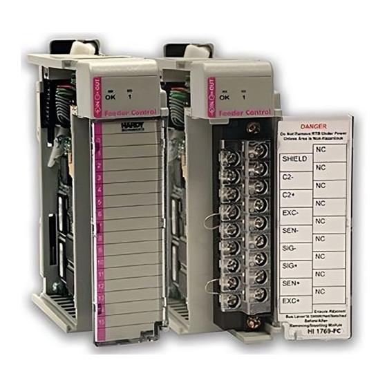
HI 1769-WS & HI 1769-2WS
WEIGH SCALE MODULE
OPERATION AND INSTALLATION
MANUAL
Corporate Headquarters
9440 Carroll Park Drive
San Diego, CA 92121
Phone: (858) 278-2900
FAX: (858) 278-6700
Web-Site: http://www.hardysolutions.com
Hardy Process Solutions Document Number: 0596-0282-01 Rev T
Copyright 2011-2013 Hardy Process Solutions, All Rights Reserved. Printed in the U.S.A. (941028)
Advertisement
Table of Contents

Related Manuals for Hardy Process Solutions HI 1769-WS


Summary of Contents for Hardy Process Solutions HI 1769-WS
- Page 1 MANUAL Corporate Headquarters 9440 Carroll Park Drive San Diego, CA 92121 Phone: (858) 278-2900 FAX: (858) 278-6700 Web-Site: http://www.hardysolutions.com Hardy Process Solutions Document Number: 0596-0282-01 Rev T Copyright 2011-2013 Hardy Process Solutions, All Rights Reserved. Printed in the U.S.A. (941028)
-
Page 2: Local Field Service
6:00 AM to 5:30 PM Pacific Standard Time) and weekends. Outside the U.S Hardy Process Solutions has built a network of support throughout the globe. For specific field service options available in your area please contact your local sales agent or our U.S. factory at +1 858-292-2710, Option 4... -
Page 3: Table Of Contents
Table of Contents HI 1769-WS & HI 1769-2WS - - - - - - - - - - - - - - - - - - - - 1-1 WEIGH SCALE MODULE - - - - - - - - - - - - - - - - - - - - - 1-1 Local Field Service - - - - - - - - - - - - - - - - - - - - - - - - - 1-2 Outside the U.S- - - - - - - - - - - - - - - - - - - - - - - - - - - 1-2... - Page 4 About the Module I/O Connector - - - - - - - - - - - - - - - -3-4 Installing the HI 1769-WS on a Din Rail - - - - - - - - - - - - - - -3-7...
- Page 5 Configuring the HI 1769-WS in RSLogix 5000 for CompactLogix - 4-7 Parameters for the HI 1769-WS Module - - - - - - - - - - - - - - - 4-10 About Parameters - - - - - - - - - - - - - - - - - - - - - - - 4-10...
- Page 6 HI 1769-WS/HI 1769-2WS WEIGH SCALE MODULE Electrical - - - - - - - - - - - - - - - - - - - - - - - - - - - - - -6-6 Mechanical Stability and Configuration Settings - - - - - - - - - - -6-7...
-
Page 7: Table Of Illustrations
SUPPRESSION CORE OPEN3-15 SUPPRESSION CORE INSTALLED3-16 HARDY HI 215IT JUNCTION BOX WIRING DIAGRAM3-16 CHAPTER 4 - SETUP4-1 MODULE LEDS HI 1769-WS SINGLE CHANNEL4-1 MODULE LEDS HI 1769-2WS DUAL CHANNEL4-2 I/O CONFIGURATION DIALOG BOX4-3 READ I/O CONFIGURATION FROM ONLINE PROCESSOR DIALOG BOX4-... - Page 8 HI 1769-WS/HI 1769-2WS WEIGH SCALE MODULE I/O CONFIGURATION DIALOG BOX4-6 I/O CONFIGURATION DIALOG BOX4-7 SELECTING COMPACTBUS LOCAL4-8 SELECT MODULE TYPE/SELECTING 1769 MODULE/GENERIC4-8 MODULE PROPERTIES DIALOG BOX/CONFIGURATION/SIZE/0 WORDS4- MODULE PROPERTIES DIALOG BOX/CONFIGURATION/SIZE/48 WORD S4-9 CONTROLLER TAGS/SLOT 14-15 CHAPTER 5 - CALIBRATION5-1...
-
Page 9: Overview
CHAPTER 1 setup, configuration, operation, communication, maintenance, and troubleshooting procedures for the Hardy HI 1769-WS & HI 1769-2WS Compact and Micro Logix I/O Weigh Scale Modules that mount on ® the Allen-Bradley CompactLogix™ and MicroLogix™... -
Page 10: About Hardy Manuals
Customer Support Department at Hardy Pro- cess Solutions Inc. Description The HI 1769-WS & HI 1769-2WS Weigh Scale Mod- ules are self-contained, microprocessor-based Con- trolLogix I/O modules with control inputs and outputs, that is designed to be easily plugged into an... -
Page 11: Waversaver
Typically, mechanical noise (from machinery in a plant environment) is present in forces larger than the weight forces trying to be detected by the module. The HI 1769-WS & HI 1769-2WS is fitted with ® WAVERSAVER technology which eliminates the effects of vibratory forces present in all industrial weight control and measurement applications. -
Page 12: Digital Volt Meter (Dvm) - Optional
HI 1769-WS/HI 1769-2WS WEIGH SCALE MODULE detects the quantity of load sensors in the system. All calibrations can be performed via ladder logic. ® ™ is a system diagnostics NTEGRATED ECHNICIAN utility. For full functionality the weigh system should include an HI 215IT series junction box. Full IT func- tionality allows the operator to rapidly troubleshoot a weighing system. -
Page 13: Auto Zero Tracking
Chapter 1 - Overview Disconnects the controller and engages an inter- nal reference signal to see if the problem is within the instrument. Disconnects the load sensors and engages an internal (in the junction box) reference signal to see if the cable between the instrument and the Junction Box is causing the problem. - Page 14 HI 1769-WS/HI 1769-2WS WEIGH SCALE MODULE...
-
Page 15: Chapter 2 - Specifications
Chapter 2 - Specifications CHAPTER 2 - SPECIFICATIONS A Brief Description of Chapter 2 lists the specifications for the HI 1769-WS Chapter 2 & HI 1769-2WS Weigh Scale Modules. Specifica- tions are listed for the standard instrument and for optional equipment. The specifications listed are designed to assist in the installation, operation and troubleshooting of the instrument. -
Page 16: Common-Mode Voltage Range
HI 1769-WS/HI 1769-2WS WEIGH SCALE MODULE Common-Mode 2.5VDC maximum (with respect to earth ground) Voltage Range Bus Input Voltage 5 VDC Bus Current Load <0.5 Amp at 5 VDC Bus Power Load < 5W at 5 VDC C2 Calibration Isolation from digital section 1000 VDC minimum. -
Page 17: Optional Equipment
Hardy Part # -RTA (HI-1769-XX-RTA if ordered sep- Termination arately) Remote Termination supports two (2) sepa- Assembly rate HI 1769-WS or HI 1769-2WS weigh scale modules. Unit includes DIN rail mounting for 35mm x 15mm DIN rail. RTA Cable Hardy Part # -C6 (HI 1769-XX-C6) Assemblies •... -
Page 18: Emi Suppression Core
HI 1769-WS/HI 1769-2WS WEIGH SCALE MODULE Parameter Default Setting ZeroTrackEnable False ZeroTolerance 10.0 lbs 10.0 AutoZeroTolerance 10.0 lbs 10.0 MotionTolerance 5.0 lbs Table 2-1: Default Parameters EMI Suppression Core Cable Diameter .250 inches Max. (6.4 mm Max) Supression Up to 500 MHz... -
Page 19: Chapter 3 - Installation
Step 3. Check to see that everything in the pack- age matches the bill of lading. You should normally have: • HI 1769-WS or HI 1769-2WS Weigh Scale Module • Operation & Installation Manual Step 4. Write down the Model and Serial number of the module. -
Page 20: And Micrologix 1500 Bank
HI 1769-WS/HI 1769-2WS WEIGH SCALE MODULE Installing the HI 1769-WS or HI 1769-2WS to an Allen-Bradley CompactLogix or MicroLogix 1500 Processor WARNING ELECTROSTATIC DISCHARGE MAY DAM- AGE SEMICONDUCTOR COMPONENTS. DO NOT TOUCH THE CONNECTOR PINS AND OBSERVE THE FOLLOWING HANDLING PRECAUTIONS: •... - Page 21 Chapter 3 - Installation Lever A Lever B Module A Module B FIG. 3-1 POSITIONING THE MODULE FOR INSTALLATION Step 2. Pull Lever B back to the unlock position. FIG. 3-2 CONNECTOR UNLOCK POSITION...
-
Page 22: Installing The Module I/O Connector
HI 1769-WS/HI 1769-2WS WEIGH SCALE MODULE Step 3. Gently slide the HI 1769-WS or HI 1769- 2WS module onto the other module. In our example we connected two Hardy HI 1769-WS Weigh Modules. Step 4. When you have the modules aligned, press Lever B towards Module A to fasten the connector to Module A. - Page 23 Chapter 3 - Installation Single Channel Pin 1 Shield1 Pin 3 C2-1 Pin 5 C2+1 Pin 7 Exc-1 Pin 9 Sen-1 Pin 11 Sig-1 Pin 13 Sig+1 Pin 15 Sen+1 Pin 17 Exc+1 Dual Channel Pin 1 Shield1 Pin 2 Shield2 Pin 3 C2-1...
- Page 24 HI 1769-WS/HI 1769-2WS WEIGH SCALE MODULE Step 4. To install the connector reverse steps 2 & FIG. 3-4 MODULE CONNECTOR INSTALLED...
-
Page 25: Installing The Hi 1769-Ws On A Din Rail
Chapter 3 - Installation FIG. 3-5 MODULE CONNECTOR REMOVED FOR EASIER CABLING Step 5. Install the cable so it allows the module door to close. Step 6. Check to be sure that the wires are securely connected before operating the module. - Page 26 HI 1769-WS/HI 1769-2WS WEIGH SCALE MODULE Rail Fasteners FIG. 3-6 RAIL FASTENERS IN RETRACTED POSITION Step 2. Place the module on the DIN rail. Step 3. While holding the module in place, press the two rail fasteners towards the center of the module until they both snap into place.
- Page 27 Chapter 3 - Installation FIG. 3-7 RAIL FASTENERS IN THE CLOSED POSITION...
-
Page 28: Load Cell Wiring Diagrams
HI 1769-WS/HI 1769-2WS WEIGH SCALE MODULE Load Cell Wiring Diagrams Industry Standard Load Cells FIG. 3-8 INDUSTRY STANDARD LOAD CELLS WIRING DIAGRAM 3-10... -
Page 29: Hardy Load Sensor With C2
THE WARRANTY VOIDED. HI 1769 Remote Provides connection points between the cable assem- Terminal bly from the HI 1769-WS module and the individual Assembly wires from the junction box(es) or load sensor(s). (See (HI 1769-XX-RT) Fig. 3-10) The RTA can be mounted on a DIN Rail. - Page 30 HI 1769-WS/HI 1769-2WS WEIGH SCALE MODULE FIG. 3-10 REMOTE TERMINAL ASSEMBLY 59mm (2.3") FIG. 3-11 RTA DIN RAIL MOUNT RTA Cable • Six (6) foot cable and schematic that connects to Assembly the HI 1769-WS module. (See Figs. 3-12& 3-13) 3-12...
- Page 31 Chapter 3 - Installation FIG. 3-12 RTA CABLE ASSEMBLY - HI 1769- FIG. 3-13 RTA CABLE SCHEMATIC - HI 1769- • Six (6) foot cable that connects to the HI 1769- 2WS. (See Figs. 3-14 & 3-15) FIG. 3-14 RTA CABLE - HI 1769-2WS 3-13...
- Page 32 HI 1769-WS/HI 1769-2WS WEIGH SCALE MODULE FIG. 3-15 RTA SCHEMATIC HI 1769-2WS EMI Suppression For CE requirements you will need to install an EMI Core Installation suppression core around the multi-strand portion of (Prt. #2547-0013) the RTA cable. (See Fig. 3-12 & 3-14)
- Page 33 Chapter 3 - Installation Latch FIG. 3-16 EMI SUPPRESSION CORE Step 4. Open the core until it is wide enough to enclose all the strands of wire. (See Fig. 3- FIG. 3-17 SUPPRESSION CORE OPEN Step 5. Place all the wire strands in the core and gently close the core until it snaps shut.
-
Page 34: Hardy Hi 215It Junction Box
HI 1769-WS/HI 1769-2WS WEIGH SCALE MODULE FIG. 3-18 SUPPRESSION CORE INSTALLED Hardy HI 215IT Junction Box FIG. 3-19 HARDY HI 215IT JUNCTION BOX WIRING DIAGRAM NOTE: When connecting the Hardy HI 215IT Junction Box you must remove the two factory installed jumpers 17&15 and 7&9 on the module install sense lines... -
Page 35: Chapter 4 - Setup
Step 2. If there is power to the module, the LEDS should be lit. (See Fig. 4-1 and 4-2) Step 3. To make any settings the LED’s should be lit for normal operation: FIG. 4-1 MODULE LEDS HI 1769-WS SINGLE CHANNEL... -
Page 36: Leds
HI 1769-WS/HI 1769-2WS WEIGH SCALE MODULE FIG. 4-2 MODULE LEDS HI 1769-2WS DUAL CHANNEL LEDS The module has a Scale LED and an OK LED associ- ated with it. The LEDs may be green, red or off. They may be steady, Fast Flashing (5 Hertz) of Slow Flash-... -
Page 37: Setting Up Communications Between The Micrologix 1500
Setting Up Communications Between the MicroLogix 1500 Processor and the HI 1769-WS & HI 1769- 2WS Weigh Scale Modules NOTE: On the side of the module you will see a label that reads either Firmware REV A or Firmware REV B,C,D etc. - Page 38 (See Fig. 4-4) FIG. 4-4 READ I/O CONFIGURATION FROM ONLINE PROCESSOR DIALOG BOX Step 5. The HI 1769-WS I/O is configured and ready to communicate with the MicroLogix 1500 Processor. Step 6. For Firmware REV B you need to double click on the module which opens the Con- nection Parameters dialog box.
-
Page 39: Alternative Setup Procedures
Chapter 4 - Setup FIG. 4-5 CONNECTION/CONFIGURATION - 48 Alternative Setup Procedures Configuring the HI 1769-WS in RSLogix 500 for MicroLogix 1500 To set up communication between the MicroLogix 1500 Processor and the Weigh Scale Module you will need to do the following in RSLogix 500: Step 1. - Page 40 HI 1769-WS/HI 1769-2WS WEIGH SCALE MODULE FIG. 4-6 EXPANDING CONTROLLER FIG. 4-7 I/O CONFIGURATION DIALOG BOX Step 3. From the I/O Configuration dialog box, under the “#” column heading, click on #1 or the next open slot number available. (See Fig. 4-8) Step 4.
-
Page 41: Configuring The Hi 1769-Ws In Rslogix 5000 For Compactlogix
“OTHER” appears under the Part # col- umn heading. (See Fig. 4-8) FIG. 4-8 I/O CONFIGURATION DIALOG BOX Step 8. The HI 1769-WS I/O is configured and ready to communicate with the MicroLogix 1500 Processor. Configuring the To set up communication between the CompactLogix... - Page 42 HI 1769-WS/HI 1769-2WS WEIGH SCALE MODULE FIG. 4-9 SELECTING COMPACTBUS LOCAL Step 2. Right click on “CompactBus Local”. A dia- log box appears. Step 3. Click on “New Module”. The “Select Module Type” dialog box appears. (See Fig. 4-10) FIG. 4-10 SELECT MODULE TYPE/...
- Page 43 Chapter 4 - Setup Step 4. From the Select Module Type dialog box, scroll down the list until you find the 1769 Module - Generic Module. Step 5. Double click on the 1769 Generic Module. Step 6. Click on the OK button. The Module Prop- erties dialog box appears.
-
Page 44: Parameters For The Hi 1769-Ws Module
HI 1769-WS/HI 1769-2WS WEIGH SCALE MODULE Step 8. Click in the Description Text Box. Type in a description of the module. Step 9. Click on the down arrow to the right of Comm Format to open the pull down list. - Page 45 Chapter 4 - Setup • #define ERRORADCONVERT 0x0001 • #define ERRORADFAILURE 0x0002 • #define STATUSINMOTION 0x0040 • #define ERRORNOCAL 0x0080 • #define ERROREEPROMWRITE 0x0100 // an error occurred when writing to non- volatile memory • #define NVRDEFAULTED 0x0200 // set if SETDEFAULTPARAMS command was given •...
-
Page 46: Configuration Parameters For The Hi 1769-Ws Module
Ref Point for C2 Calibration TABLE 4-1: PARAMETERS Configuration The HI 1769-WS & HI 1769-2WS are equipped with Parameters for the Firmware REV B have 48 words of configuration HI 1769-WS Module data. The HI 1769-WS Firmware REV B has 48 words of configuration data for CompactLogix and Extended Data on MicroLogix, 24 words per channel. - Page 47 Chapter 4 - Setup The configuration data is sent from the PLC to the HI 1769-WS module at power-up. The module uses these parameters provided that: The parameters are in the correct range. Ille- gal values will be rejected. The “CopyConfig” word (0 for channel 0, 24 for channel 1) is set to 1.
- Page 48 HI 1769-WS/HI 1769-2WS WEIGH SCALE MODULE Offset (In Parameter Data Type Words) Ch0CalLowWeight REAL or INT Ch0ROCtimebase Ch0CopyCal Ch0calzerocount DINT Ch0CalHighCount DINT Ch0Spare2 Ch0Spare3 Ch1CopyConfig Ch1ChanActive Ch1Metric Ch1Waversaver Ch1NumAverages Ch1ZeroTrackEnable Ch1AutoZeroTolerance REAL or INT Ch1MotionTolerance REAL or INT Ch1ZeroTolerance REAL or INT...
-
Page 49: Commands
Chapter 4 - Setup parameters in the form above. When you expand the slot you selected for the these parameters they will look like the following: Local:1:C.Data[0] Local:1:C.Data[1] Local:1:C.Data[2] Local:1:C.Data[3] ...and so on These correspond directly to the parameters in the table above. -
Page 50: Command Operation
HI 1769-WS/HI 1769-2WS WEIGH SCALE MODULE input table is called the command STATUS. Nor- mally, a 0 value of STATUS means that the command completed OK and a non-zero status indicates some kind of error. Command Step 1. To start a command, place the command... -
Page 51: Command Table
Chapter 4 - Setup Command Table Required Output Table Values Input Table Response Command Written by User (PLC) From Weigh Scale NOCMD (no command) O:0 = 0 I:0 = 0 O:1-0:15 (unused) I:1 = COMMAND STATUS = Give this command to read weight from the module. - Page 52 HI 1769-WS/HI 1769-2WS WEIGH SCALE MODULE Required Output Table Values Input Table Response Command Written by User (PLC) From Weigh Scale WRITEMETRIC O:0 = 3 I:0 = 3 O:1 - unused I:1 = COMMAND STATUS Writes the Metric O:2 - unused I:2-I:15 See NOCMD, Parameter.
- Page 53 Chapter 4 - Setup Required Output Table Values Input Table Response Command Written by User (PLC) From Weigh Scale WRITEPARAM0 O:0 = 0x67 I:0 = 0x67 0x67 O:1 = unused I:1 = COMMAND STATUS Write a block of O:2 = ChanActive I:2-I:15 See READPARAM0 parameters: O:3 = Metric...
- Page 54 HI 1769-WS/HI 1769-2WS WEIGH SCALE MODULE Required Output Table Values Input Table Response Command Written by User (PLC) From Weigh Scale READPARAM0 O:0 = 0x69 I:0 = 0x69 0x69 O:1-O:15 = unused I:1 = 0 Read a parameter block. I:2 = ChanActive...
- Page 55 Chapter 4 - Setup Required Output Table Values Input Table Response Command Written by User (PLC) From Weigh Scale STABILITYTEST O:0 = 0x6B I:0 = 0x6B 0x6B O:1 = signal to switch in I:1 = COMMAND STATUS Switch in a specified signal O = onboard reference signal in place of the normal load 1-4 = load cell signals on IT-JBOX...
- Page 56 HI 1769-WS/HI 1769-2WS WEIGH SCALE MODULE TESTRESULTS O:0-0x6C I:0x6C 0x6C O:1-15 (unused) I:1 = return to zero test result, Report the results of a previous bit coded: INTEGRATED TECHNICIAN test. No new • Bits set to 1 indicate non- test is performed return to zero.
- Page 57 Chapter 4 - Setup WEIGHSYSTEST O:0=0x6D I:0 = 0x6D 0x6D O:1 = number of sensors I:1 = number of sensors Perform an INTEGRATED O:2-15 (unused) I:2-15 are weight values, TECHNICIAN test. scaled according to the Metric Parameter value I:2 = combined gross weight, I:3 = combined gross weight, I:4 = gross weight on load sensor #1, LSW...
-
Page 58: Calibration Setup Procedures
HI 1769-WS/HI 1769-2WS WEIGH SCALE MODULE READC2SERIALNUM O:0 = 0x70 I:0 = 0x70 0x70 O:1 = SENSOR NUMBER I:1 = COMMAND STATUS Read data from a C2 sensor. (0-7) I:2-9 = Serial Number The C2SEARCH command I:10 = Sensitivity, LSW... -
Page 59: Setting The Zero Tolerance Value
Chapter 4 - Setup Setting The Zero Sets the range of weights so that the Zero Command Tolerance Value works, as an offset of the calibrated Zero. Setting the Auto When the Auto Zero Tolerance is entered, and Auto Zero Tolerance Zero Tracking is enabled, any weight within the Value entered tolerance of zero and not in motion, will cause... - Page 60 HI 1769-WS/HI 1769-2WS WEIGH SCALE MODULE 4-26...
-
Page 61: Chapter 5 - Calibration5-1
A Brief Description of Chapter 5 pertains to the calibration procedures for Chapter 5 the HI 1769-WS and HI 1769-2WS Weigh Scale Modules. Alternatives to any procedures either implied or explicitly contained in this chapter are not recommended. In order for the Weigh Module to work properly, it must be calibrated prior to operation. -
Page 62: Electrical Check Procedures
HI 1769-WS/HI-1769-2WS WEIGH SCALE MODULE A load cell must be mounted in such a way that 100% of the load (Vessel w/ Contents) is vertically passed through a load cell. (See Fig. 5-1) Check to see that nothing is binding the load cell. - Page 63 Chapter 5 - Calibration The Weigh Module is designed to sup- ply 5 VDC excitation to as many as four (4) 350 Ohm load cells/points. The expected output from each load cell/point depends on the mV/V rating of the load cell/point and the weight. For example, a 2mV/V load cell/point will respond with a maximum of 10 mVDC at full weight capacity of the...
-
Page 64: Load Check
HI 1769-WS/HI-1769-2WS WEIGH SCALE MODULE FIG. 5-2 MILLIVOLTS/WEIGHT SCALE Based on the example, the operating range for this scale is 5-10 mVDC with a 500 pound weight range. Understand that after zeroing the instrument, the 0 reading refers to the zero reference point and not absolute 0 mVDC or absolute 0 weight. -
Page 65: C2 Calibration
C2 Calibra- tion. The Ladder Logic example is avail- able on the Hardy Web Site: http://www.hardysolutions.com Step 3. Click on “Support”. Step 4. Click on “Sample Programs”. Step 5. You will find the sample programs under the HI 1769-WS Heading. -
Page 66: Hard Calibration
Click on Sample Programs. Click on the pull down menu for the product you are calibrating. Click on the Ladder Logic Example for the HI 1769-WS Weigh Module, Hard Calibration. Step 4. If you do not have access to the Internet,... -
Page 67: Chapter 6 - Troubleshooting
All maintenance personnel and users should be familiar with Chapter 6 before attempting to repair the HI 1769-WS. Scale LED is Flashing Solution: Check all the connections to be sure they are securely fastened. - Page 68 HI 1769-WS/HI 1769-2WS MANUAL Keep flexures on the horizontal Vertical flexures should be avoided Do not use flexures to correct for misaligned piping Do not use hose flexures to make right angle bends Non-flexed piping should have an unsupported horizontal run using a ratio of 36 times it's diameter.
-
Page 69: Load Sharing And Load Sensor Checkout
CHAPTER 6 - Troubleshooting Load Sharing and See Figure 6-2 Load Sensor Checkout NOTE: On balancing load cells, the overall objective is to insure each load cell sees a positive millivolt reading. When weight is evenly applied, all load cells signals should increase the same amount. - Page 70 HI 1769-WS/HI 1769-2WS MANUAL Does the mV signal increase in a positive direction. If you receive a negative results, check if load cell is mounted correctly. The arrow goes with the direction of force. If there isn't an arrow, you must manually verify the correct direction.
-
Page 71: Guidelines For Instabilities On Formerly Operating Systems
CHAPTER 6 - Troubleshooting Guidelines for See Figure 6-3 Instabilities on Formerly Operating Systems Check for Electrical Stability OK ? Check for Mechanical Stability OK ? Check for Mechanical Stability OK ? Contact Hardy Instruments Ser vice Center FIG. 6-3 GUIDELINES FOR INSTABILITIES ON FORMERLY OPERAT- ING SYSTEMS... - Page 72 HI 1769-WS/HI 1769-2WS MANUAL Electrical See Figure 6-4 Electrical B1.1 Physical Grounding - All common equipment share a common ground point. Keep the ground cable length to earth ground as short as possible. Install a new ground rod if the cable length is excessive.
- Page 73 CHAPTER 6 - Troubleshooting Mechanical Stability See Figure 6-5 and Configuration Settings Mechanical Stability Vessel - When inpspecting a vessel keep in mind, the Center of Gravity (COG) should be low and centered equally over all the load cells. Insure the load is directly over or under the load point to avoid side-loadin. Make sure there isn’t any side loading from piping or external forces.
- Page 74 HI 1769-WS/HI 1769-2WS MANUAL...
- Page 75 Index Index Symbols “dead” loads 1-3 “OTHER” 4-7 “The Button” 1-3 Numerics 16 bit integer 4-10 1756 RTA (Remote Termination Assembly 2-3 1769 Generic Module 4-9 2 Channel HI 1769-2WS 2-1 32 bit float 4-10 32 bit IEEE float 4-10 32 bit integer 4-10 32 bit integers 4-10 350 Ohm load cells/points 5-3...
- Page 76 HI 1769-WS/HI 1769-2WS MANUAL Allen-Bradley’s RS Logix 5000 4-1 analog to digital converter 1-3 Approvals 2-2 Auto Zero Tolerance 1-5 Auto Zero Tracking 1-5, 4-25 Averages 2-1 Backplane Current Load 2-2 Backplane Input Voltage 2-2 Backplane Power Load 2-2 Before signing 3-1...
- Page 77 Index Common-Mode Rejection 2-1 Common-Mode Voltage Range 2-2 CompactBus Local 4-8 CompactLogix 3-2 CompactLogix Processor 4-7 Configuration 1-2 configuration data 4-13 Connection Parameters dialog bo 4-4 Connection Parameters/Configuration 4-10 Connection Parameters/Extra Data Length 4-3 Connection Parameters/Input 4-10 Connection Parameters/Output 4-10 ControlLogix I/O 1-2 Conversion Rate 2-1 Customer Support Department 1-1...
- Page 78 Hardy Instruments C2 certified load sensors 1-3 Hardy Load Sensor with C2 3-11 HI 1756 Remote Terminal Assembly 3-11 HI 1769-WS Compact and Micro Logix I/O Weigh Scale Modules 1-1 HI 1769-XX-RT 3-11 HI 215IT Junction Box 1-4 HI 215IT Series Junction Box 1-4, 2-3, 3-4...
- Page 79 Index Installing the HI 1756-WS (-2WS) 3-2 Installing the HI 1769-WS on a Din Rail 3-6, 3-7 Installing the Module I/O Connector 3-4 integrated communication 1-1 Integrated Technician 5-4 Integrated Technician™ 1-4 IT 1-4 ladder logic 1-1 ladder logic display 5-4...
- Page 80 HI 1769-WS/HI 1769-2WS MANUAL mV/V rating 5-3 mV/V readings 1-4 Name Text box 4-9 NEVER touch the connector pins 3-2 Non-Linearity 2-1 OK Module Status LED 4-2 open the suppression core 3-14 Operating Temperature Range 2-2 Optional Equipment 2-3 over sizing of load cells/sensors 1-3...
- Page 81 Setting the Span Weight Value 4-25 Setting the WAVERSAVER Value 4-25 Setting The Zero Tolerance Value 4-25 Setting Up Communications Between the MicroLogix 1500 Processor and the HI 1769-WS Weigh Scale Module 4-3 single module 1-2 Specifications 1-2 Specifications for a Standard HI 1756-WS 2-1...
- Page 82 HI 1769-WS/HI 1769-2WS MANUAL Weighing System Tests 1-4 wrist-strap grounding device 3-2...
Need help?
Do you have a question about the HI 1769-WS and is the answer not in the manual?
Questions and answers