Toshiba GR200 Series Instruction Manual
Hide thumbs
Also See for GR200 Series:
- Instruction manual (1770 pages) ,
- Instruction manual (1176 pages) ,
- Instruction manual (22 pages)
Advertisement
Quick Links
6F2S1915 (Rev. 0.46)
Instruction manual
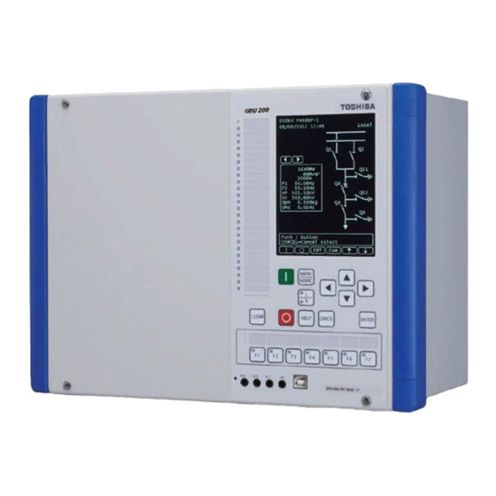
Distance Protection IED
GR200 series (GRZ200)
GRZ200---
S, G, and T positions
TOSHIBA ENERGY SYSTEMS & SOLUTIONS CORPORATION
Notice: GRZ200 manual is issued for '031' and '032'
software code, which you can identify at 'S, G, and
T positions' on Software nameplate.
Advertisement


Need help?
Do you have a question about the GR200 Series and is the answer not in the manual?
Questions and answers