
Related Manuals for RKI Instruments GX-94


Summary of Contents for RKI Instruments GX-94
- Page 1 GX-94 Operator’s Manual Part Number: 71-0008RK Edition: Revision P2 Released: 6/10/2002 RKI Instruments, Inc. 1855 Whipple Road Hayward, CA 94544 800-754-5165...
- Page 2 WARRANTY RKI Instruments, Inc., warrants the GX-94 sold by us to be free from defects in materials, workmanship, and performance for a period of one year from the date of shipment from RKI Instruments, Inc. Any parts found defective that warranty period will be repaired or replaced, at our option, free of charge.
-
Page 3: Table Of Contents
Preparation ........13 Starting Up the GX-94 ......13 Normal Operation . - Page 4 Preparation........34 Calibrating the GX-94......34 Setting the Date and Time .
-
Page 5: Introduction
INTRODUCTION The RKI Model GX-94 is an advanced gas detection instrument in use internationally for personal protection in a variety of industries. The GX- 94 is rugged, compact, convenient, and offers a full range of features, including: • Simultaneous detection of two, three, or four gases. The standard configuration is combustible gas in the %LEL range (HC,) oxygen... -
Page 6: Specifications
SPECIFICATIONS Table1 lists physical and environmental specifications for the GX-94. Table 2 lists specifications for the GX-94’s sensors and channels. Table 1: GX-94 Specifications Target Gases Combustible Gas (HC); Oxygen (O ), Carbon Monox- ide (CO), Hydrogen Sulfide (H Case... - Page 7 31 - 100 ppm 51 - 150 ppm ± 5% LEL ±5 ppm ± 15 ppm 151 - 500 ± 25 ppm 1 Alarms are user adjustable. See Viewing and Setting Alarms in the setup mode section. GX-94 Operator’s Manual Page 6...
-
Page 8: Description
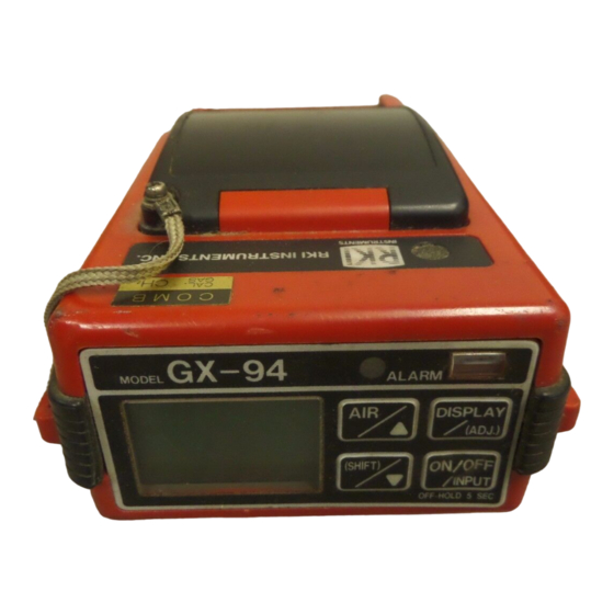
Alarm LED Light Sensor Control Button, 4X Display GX-94 Model Alarm Display (ADJ.) (Shift) ON/OFF INPUT Figure 1: GX-94 Control Panel The control panel is at the front of the GX-94 for easy access when the Page 7 GX-94 Operator’s Manual... - Page 9 GX-94 is carried or clipped on a belt. It contains the display, the touch- pad buttons that control the many functions of the GX-94, the Alarm LED, and the light sensor. The display is to the left of the buttons and simultaneously shows the gas readings for all active channels.
-
Page 10: Battery Compartment
Flange, 2X Figure 2: Top & Side views of the GX-94 Battery Compartment The battery compartment is located on the top of the GX-94. A tethered battery cover allows easy battery replacement. It is tethered to the inter- face port cover. -
Page 11: Interface Port
The GX-94 uses two “C” size cells. Alkaline batteries will run the GX-94 for approximately 12 hours of non-alarm operation. Rechargeable nickel-cadmium batteries will run it for approximately 8 hours of non- alarm operation. The GX-94 does not include a charging jack, so rechargeable batteries must be removed from the GX-94 and charged separately. -
Page 12: Sensors
CO sensor. Sensors The sensors are located inside the case in the top rear of the GX-94 behind the diffusion ports. A rubber sensor gasket is installed over the sensors and forms a seal between the sensors and the inside of the case to prevent any moisture or dirt which may enter the diffusion ports from entering the inside of the GX-94. -
Page 13: Circuit Boards
The toxic sensors are electrochemical cells, which react to gas in the atmosphere, producing a current proportional to the concentration of gas. The current is converted by the GX-94’s circuitry into a measure- ment of gas concentration. Circuit Boards The GX-94 circuit boards analyze, record, control, store, and display the information collected. -
Page 14: Operation
GX-94. Note The screens illustrated in this section are of a four gas GX- 94. If you have a two gas or a three gas GX-94, some of your screens will look slightly different. Preparation Normally the GX-94 requires little preparation before use. If you have one of the available sample drawing accessories, see the Accessories section for installation instructions. - Page 15 The Battery Voltage screen displays. The Battery Voltage screen displays the minimum usable and actual battery voltage. If the battery voltage is too low, the GX-94 will not continue. BATTERY MIN. 2.3V BATTERY NOW 2.9V...
- Page 16 O2 20. H2S 0.0PPM CO 0PPM 2. Verify that the GX-94 is operating properly. Breathe out over the diffusion grill of the instrument until the oxygen reading drops below the low alarm level. The audible alarm for oxygen deficiency will sound, the ALARM LED will blink, and “O2” will flash on the display.
-
Page 17: Normal Operation
IN A POTENTIALLY HAZARDOUS LOCATION Normal Operation The GX-94 will continuously monitor the ambient air and display the tar- get gas concentrations present. If the GX-94 is taken into a low-light environment, the display backlight will automatically turn on. Turning Off the GX-94 To turn off the GX-94, press and hold down the ON/OFF/INPUT button until the display goes blank, approximately five seconds, then release... -
Page 18: Alarms
field for that gas. 5. Time Weighted Average (TWA) Alarm, H S and CO Only If the average toxic gas level detected over the last 8 hours exceeds the TWA alarm setting, a pulsing audible alarm will sound Page 17 GX-94 Operator’s Manual... - Page 19 If the full scale value is exceeded for any channel, the alarm tone and LED will be continuous. The display will show “MAX” in the gas reading field for that channel. 8. Low Battery When the battery charge drops near the lower limit, the GX-94 displays the following screen. 0LEL Low Battery Warning •...
- Page 20 GX-94 alerts you with audible and visual alarms. If a sensor fails during operation, the GX-94 will sound a steady tone, the alarm LED will be on, and it will display the following screen with the failed sensor in parentheses (in this example, the...
-
Page 21: Resetting Alarms
To continue using the GX-94, turn it off, then follow the start-up sequence. During start-up, the Fail screen will display and the buzzer and alarm LED will pulse momentarily. When the normal operation screen comes up, the display will indicate the failed sensor as “xxx”:... -
Page 22: Display Mode
DISPLAY MODE The GX-94 has four operating modes: normal operation, display mode, setup mode, and calibration mode. With the GX-94 in display mode, you can: • display, enter, or update user and station ID’s • display peak readings • display average readings •... -
Page 23: Peak Screen
(lower for O ) level is detected, or the unit is turned off. When the Lunch Break RESUME option is selected during startup, the the GX-94 remembers the peak readings from the last time the unit was 0LEL 0PPM GX-94 Operator’s Manual... -
Page 24: Average Screen
The Elapsed Time screen shows the time in minutes since the unit was turned on. When the Lunch Break RESUME option is selected during start-up, the GX-94 will include the time from the last session when it displays the time in operation. TIME IN... -
Page 25: Stel Screen
TWA was cleared, the average is still calculated over 8 hours, with the missing time assigned a 0 value for readings. When the Lunch Break RESUME option is selected during start-up, the GX-94 will include the TWA from the last session. 0PPM GX-94 Operator’s Manual... -
Page 26: Battery Voltage Screen
MIN. 2.3V BATTERY NOW 2.8V Note The GX-94 automatically checks battery voltage during start- up; if the measurement is below 2.3V, the GX-94 will not operate. Time/Date/Temperature Screen This function shows the current time, date, and ambient temperature, for example:... -
Page 27: Clear Data Logger Screens
The remaining log time screen shows the time remaining until the data logger memory is full. The remaining time depends upon the logging frequency and how many channels are active. Press DISPLAY/(ADJ.) once more to return to normal operation. LOG TIME 15.0 HOURS REMAINING GX-94 Operator’s Manual Page 26... -
Page 28: Setup Mode
SETUP MODE The advanced microprocessor program in the GX-94 allows the user to select and adjust many of the detection and data logging features. In setup mode you can: • reset the non-volatile RAM to default values • update the gas combination •... -
Page 29: Entering Setup Mode
(SHIFT)/ buttons. Entering Setup Mode 1. Take the GX-94 to a fresh air location—the instrument does not detect gas while in setup mode. 2. If it is not already off, turn the GX-94 off. 3. Hold down the AIR/ and (SHIFT)/ buttons simultaneously, then press ON/OFF/INPUT. -
Page 30: Updating The Gas Combination
Gases selected in this operation will be displayed throughout all setup and normal display screens. Viewing & Setting Alarms (3. SET ALARM) Sets the alarm levels for gases detected by the GX-94. Press AIR/ change the alarm level for a single gas, or DISPLAY/(ADJ) to skip that channel. -
Page 31: Setting The Serial Number
2. Press and hold briefly AIR/ to raise the reading, or (SHIFT)/ lower the reading. (The reading changes in increments of one degree Celsius). 3. Press ON/OFF/INPUT to accept the displayed reading and exit the SET TEMP menu. GX-94 Operator’s Manual Page 30... -
Page 32: Setting The Logging Frequency
Toggles alarm logic between self-resetting (default) and latching alarms by turning latching ON or OFF. When Latching is set to OFF (self-reset- ting), the GX-94 automatically resets the a gas alarm when the gas reading falls below (or rises above for oxygen) the alarm point. When Latching is set to ON, the user must press DISPLAY/(ADJ.) to reset the... -
Page 33: Setting The Data Logging Alarm
Setting the Data Logging Alarm (11. SET LOG ALARM) When the Data Logger memory capacity has been filled to the percent- age selected here, the GX-94 alerts you. Default setting is off, with a range of 1 - 100%. Tip: hold AIR/ or (SHIFT)/ to scroll rapidly through values. -
Page 34: Calibration Mode
A typical calibration frequency is once per month. You can set the GX-94 to notify you when it is due for calibration (see Setting the Calibration Reminder in the setup mode section). -
Page 35: Preparation
fixed flow regulator and RKI Four Gas Cylinder. It also includes instructions for calibration with individual gas sources. Preparation 1. Take the GX-94 to a non-hazardous location with fresh-air condi- tions. 2. Turn on the instrument and allow one minute to warm up. - Page 36 The GX-94’s calibration menu includes two methods of calibration: auto calibration or single calibration. • Auto Calibration: This method allows you to calibrate all four sensors simultaneously. It is designed for use with the RKI Four gas Calibration Cylinder and is the quickest and easiest method to calibrate the GX-94.
- Page 37 ON/OFF/INPUT button to set the calibration for each channel to the programmed values. If a sensor(s) cannot be calibrated to the proper value, FAIL PUSH AIR displays and the GX-94 lists the sensor(s) that failed to GX-94 Operator’s Manual Page 36...
- Page 38 11. AUTO CAL END displays, then the Calibration menu displays. 12. Unscrew the regulator from the cylinder. 13. Remove the adapter plate from the GX-94. 14. Press the SHIFT/ button to place the prompt next the 7.RETURN menu option, then press the ON/OFF/INPUT button to return to normal operation.
- Page 39 AIR/ button to increase the reading, or the (SHIFT)/ button to decrease the reading. The GX-94 will beep each time a switch is pressed. 4. When the reading is correct, press the ON/OFF/INPUT button. The HC CAL. END...
-
Page 40: Setting The Date And Time
Setting the Date and Time The number 6 option in the calibration menu is SET DATE/TIME. Use this item to set the current date and time for the GX-94. From the normal operation screen, press and hold the (SHIFT)/ but- ton, then press the DISPLAY/(ADJ.) button to enter Calibration Mode. - Page 41 12 hour clock. 5. After the minutes are entered, press ON/OFF/INPUT to return to the main menu. 6. Press (SHIFT)/ to scroll to the last menu item, 7 RETURN. 7. Press ON/OFF/INPUT to return to normal operation. GX-94 Operator’s Manual Page 40...
-
Page 42: Maintenance
(see Alarms, Low Battery). WARNING TAKE THE GX-94 TO A NON-HAZARDOUS LOCATION BEFORE REPLACING THE BATTERIES. 2. To replace the batteries, unscrew the battery compartment cover retaining screw and remove the cover. Remove the batteries and verify that the battery compartment and electrical contacts are clean. -
Page 43: Lithium Memory Backup Battery
Lithium Memory Backup Battery The memory backup battery is a 3.0 volt lithium battery which protects against loss of the GX-94’s memory when the main batteries are dead or removed. The memory backup battery typically lasts for 5 years. Replace the memory backup battery every 5 years or if you notice that the GX-94 is losing logged data when the main batteries are changed. -
Page 44: Charcoal Filter
6. Install a fresh battery in the battery holder. Use a CR2032 3.0 volt coin type lithium battery. See the Parts List at the end of this man- ual for a replacement battery available from RKI Instruments, Inc. 7. Reinstall the cover, belt clip, and screws. -
Page 45: Sensor Maintenance
The GX-94 sensors are easy to replace but contain no user serviceable parts. For genuine RKI sensors, call RKI or your local distributor. All sensors are covered by a limited warranty;... - Page 46 Allow up to 1/2 hour after the toxics sensors have been replaced to show a normal response, then calibrate. Sensor Replacement GX-94 Shown w/out Combustible (HC) Sensor Top Case Oxygen Sensor Sensor Gasket H2S Sensor C O Sensor Figure 5: GX-94 Sensors Page 45 GX-94 Operator’s Manual...
- Page 47 1. Take the GX-94 to a non-hazardous location and turn the power off. 2. Remove the four (4) Phillips screws from the bottom of the instru- ment. (Two in the belt clip and two next to the label.) 3. Pull the top and bottom case apart where the rubber cushion cov- ers the seam.
-
Page 48: Accessories
The pump is easy to install and use, and is built to give years of dependable service. Installing the Pump 1. Slide the pump onto the sensor end of the GX-94, as shown in Fig- ure 6. Probe... - Page 49 3. Connect the sample hose and probe to the pump inlet. Using the GX-94 with the Pump 1. Turn on the GX-94 and slide the pump power switch to the ON position. Verify that the pump is running (low humming sound).
- Page 50 flow to the pump (Low Flow failure). a. Unscrew the probe handle. b. Remove and discard the clogged filter. Replace with a cotton filter. c. Re-install the probe handle and test the pump assem- bly. Page 49 GX-94 Operator’s Manual...
-
Page 51: Parts List
PARTS LIST Table 4 lists replacement parts and accessories for the GX-94. Table 4: Parts List Part Number Description 06-1248RK Tubing, for calibration kit (order by the foot) 13-0190RK Shoulder strap 20-0307RK Vinyl carrying case for instrument only 20-0602RK Waterproof carrying case for instrument and accessories... - Page 52 Hose,10 ft., polyurethane, for use with pump or aspirator adapter 80-0150RK Probe, for use with pump or aspirator adapter 81-1169RK GX-94 pump adapter with 10 ft. hose and probe 81-0090RK-01 Calibration cylinder, 3-gas,50% LEL CH /12% Oxy/50 ppm CO, nitrogen balance, 34 liter...
Need help?
Do you have a question about the GX-94 and is the answer not in the manual?
Questions and answers