Table of Contents
Advertisement
Quick Links
Advertisement
Table of Contents

Related Manuals for Fellowes ESI Victory 3V-LX-C4848-24 Series


Summary of Contents for Fellowes ESI Victory 3V-LX-C4848-24 Series
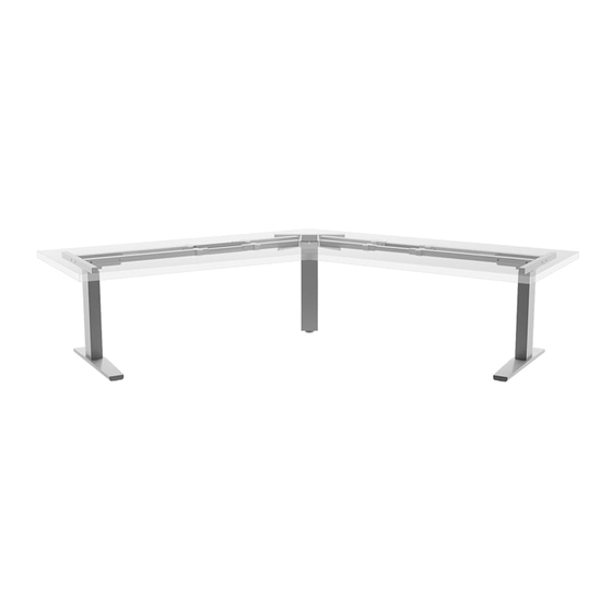
- Page 1 Victory LX 3-Leg ™ Assembly instructions Electric height adjustable table base Model # 3V-LX-C4848-24-___ Model # 3V-LX-C4848-30-___ Model # 3V-LX-C4836-24-___ Model # 3V-LX-C4836-30-___ Model # 3V-LX-C3636-24-___ Model # 3V-LX-C3636-30-___ ___ = SLV, BLK or WHT...
-
Page 2: Table Of Contents
VictoryLX 3-leg Components and tools Caution • Hand tighten all hex head screws. Use power drill on self-tapping screws only. table thickness • Always check that screws used to attach components to the worksurface are not too long for the thickness of the table. Please review these instructions before beginning the installation. -
Page 3: Left Frame Segment
VictoryLX 3-leg Assembly Step #1: attach top supports to frame short end longer channel The two top supports are left and right specific. The short end of each top support must be on the same side of the frame as the longer frame channel at the open end of the frame segment. •... - Page 4 VictoryLX 3-leg Assembly Step #3: position frame on table • Expand the cross channels to position the top supports 1" from the left and right edges of the table. — Center the mounting tabs on the U-tubes to be sure each tube can be captured by the set screws. —...
-
Page 5: M5X25 #2 Phillips Round Head
VictoryLX 3-leg Assembly Step #4: attach frame to table • Use the M4.8X22 #2 Phillips round head screws to secure the frame to the underside of the worksurface. — Use four screws for each top support, two screws for each cross support, one screw for each mounting tab, and six screws for the center leg bracket. •... -
Page 6: M6X15 Socket Cap
VictoryLX 3-leg Assembly Step #6: attach center leg to frame glide • Position the center leg (the one with the glide attached) into the center leg bracket, similar to the way the outer legs were positioned. — First lower the protrusions on the motor housing into the notches. —... - Page 7 VictoryLX 3-leg Assembly Step #8: attach digital keypad • Attach the digital keypad using the three M3x20 #1 Phillips round head screws. • Install the keypad in the “expanded” position. Pull the keypad away from the M3x20 #1 Phillips mounting bracket to expand it. round head align with •...
-
Page 8: Cord Clips
VictoryLX 3-leg Assembly Step #11: initialize the system press and hold UP and DOWN buttons • Press and hold the UP s and DOWN t buttons simultaneously for more than 3 seconds. — The legs will begin to move down at half speed of normal operation. •... - Page 9 VictoryLX 3-leg Assembly Step #14: turn the table upright WARNING: Lifting hazard. Single person lift could cause injury. Use assistance when moving or lifting. • With the assistance of a helper, turn the table upright and place it in its final position. IMPORTANT: There must be 1" (25mm) of clearance on all sides of the worksurface (and other moving parts) to ensure free, unobstructed movement.
- Page 10 VictoryLX 3-leg Operation digital DOWN button display button button Important • Before operating the table, the initialization procedure must be completed. See Step 11 on page 8. memory buttons General operation Upper stop position • Move the table up or down by pressing UP s or DOWN t until the •...
- Page 11 VictoryLX 3-leg Operation Changing the height display units Adjust gyro anti-collision sensitivity • There are 2.54 centimeters per inch. This makes it easy to tell what • The default anti-collision sensitivity is G-1. To increase or decrease the current display units are. For example, if the table is about three the sensitivity of the table to obstacles in the path of its movement: feet high, the display will read approximately either 36.0 (inches) or —...
- Page 12 PURCHASE. ESI’s sole obligation under this warranty or any implied warranty, and the purchaser’s sole remedy, is limited to the repair or replacement, at ESI’s option, of the product or any defective part. Costs (such as installation, labor fees or express shipping) incurred due to replacement of products are not covered under warranty. IN NO EVENT SHALL FELLOWES, ITS AFFILIATES, SUBSIDIARIES, RELATED ENTITIES OR THEIR RESPECTIVE OFFICERS, DIRECTORS, OR EMPLOYEES, BE LIABLE FOR INCIDENTAL, CONSEQUENTIAL, PUNITIVE, EXEMPLARY, OR SPECIAL DAMAGES.
Need help?
Do you have a question about the ESI Victory 3V-LX-C4848-24 Series and is the answer not in the manual?
Questions and answers