
Related Manuals for Fellowes esi Brisa 2B-C48 Series


Summary of Contents for Fellowes esi Brisa 2B-C48 Series
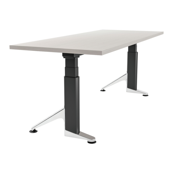
- Page 1 Brisa ™ assembly and operation instructions electric table base model 2B-C48-__-___ __ = color combination (shroud/feet) ___ = SLV, BLK or WHT (column and frame)
-
Page 2: Components And Tools
Brisa electric table base components and tools ™ caution • When drilling holes for the wood screws, guard against drilling through the top of the worksurface. work • Always check that screws used to attach components to the worksurface surface are not too long for the thickness of the surface. - Page 3 Brisa electric table base assembly ™ step 1: position frame on table With the table top facing down on a soft, clean surface, arrange the frame as shown below. The short end of the top supports must be toward the rear. •...
- Page 4 Brisa electric table base assembly ™ step 3: attach legs to frame • Remove the cotter pin from each cam lock and save it for use later in this step. • Position each leg. cam lock — First lower the protrusions on the motor housing into the notches. —...
- Page 5 Brisa electric table base assembly ™ step 5: insert shroud assemblies over legs • Slide the shroud assemblies over the legs with the cutout portion of the shroud toward the front, as shown. • Lower the shroud all the way down to the motor end of the legs.
- Page 6 Brisa electric table base assembly ™ step 7: attach shrouds to feet • Raise each shroud up to the foot. Be sure the edges of the shroud are flush with the edges of the foot. • Attach the shroud with one M4x15 #2 Phillips pan head screw per foot. The screw is self-tapping; use sufficient torque to tighten it securely, but be careful not to strip the shroud extrusion.
- Page 7 Brisa electric table base assembly ™ step 8: attach cord-organizing troughs • Two troughs may be installed to help organize the cords and cables. M4.8x22 • Peel the backing from the double-sided tape on the bottom of #2 Phillips round head the troughs.
- Page 8 Brisa electric table base assembly ™ step 10: attach control unit • Place the control unit between the cross channels. Position it so that the cable from the keypad can reach the control unit and the motor cables can control extend from the control unit to both motors.
-
Page 9: Step 13: Test Operation
Brisa electric table base assembly ™ step 12: use keypad to initialize the system keypad • Press and hold the star and gear buttons simultaneously for more than six seconds. The legs will begin to move down at half the speed of normal operation. star gear •... -
Page 10: General Operation
Brisa electric table base operation ™ CAUTION: The initialization procedure star gear button button must be completed before operating the table. See Step 12 on page 9. keypad lever lift up or press down LED height display (inches or centimeters) general operation top height limit •... -
Page 11: Error Codes
Brisa electric table base operation ™ height display units leveling To change the height display from inches to centimeters: To correct the gravity reference: • Touch the gear button six times. The display reads “F01”. • Touch the gear button six times. The display reads “F01”. •... - Page 12 PURCHASE. ESI’s sole obligation under this warranty or any implied warranty, and the purchaser’s sole remedy, is limited to the repair or replacement, at ESI’s option, of the product or any defective part. Costs (such as installation, labor fees or express shipping) incurred due to replacement of products are not covered under warranty. IN NO EVENT SHALL FELLOWES, ITS AFFILIATES, SUBSIDIARIES, RELATED ENTITIES OR THEIR RESPECTIVE OFFICERS, DIRECTORS, OR EMPLOYEES, BE LIABLE FOR INCIDENTAL, CONSEQUENTIAL, PUNITIVE, EXEMPLARY, OR SPECIAL DAMAGES.
Need help?
Do you have a question about the esi Brisa 2B-C48 Series and is the answer not in the manual?
Questions and answers