Table of Contents
Advertisement
Advertisement
Table of Contents

Related Manuals for Inter-m CA-8320


Summary of Contents for Inter-m CA-8320
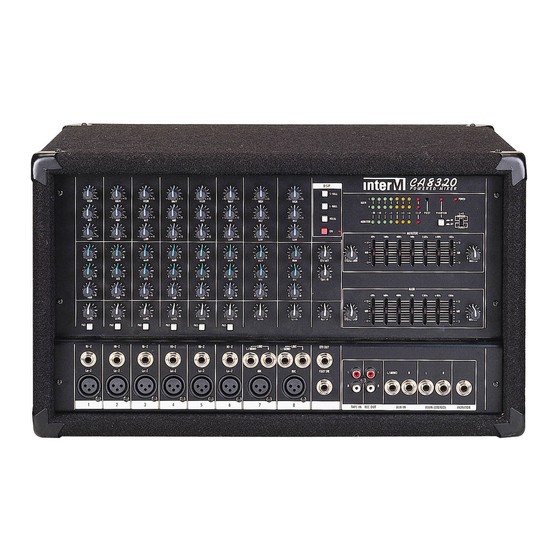
- Page 1 CA-8320 Powered Mixer Copyright 2004 Inter-M Corporation...
-
Page 2: Table Of Contents
Welcome ... 3 Unpacking ... 3 Warnings ... 3 Operation... 5 Features ... 6 Front Panel Controls... 7 Channel Section... 7 Digital Effects Section... 8 Effects Section ... 8 Tape In Section... 9 Aux In Section... 9 Monitor Section ... 10 Main Section... -
Page 3: Welcome
A personal welcome to you from the management and employees of Inter-M Thank you for purchasing this fine Inter-M product. All of us here at Inter-M are dedicated to providing you with the highest quality products and the best value. - Page 4 CA-8320 Powered Mixer 8. Do not install near any heat sources such as radiators, heat registers, stoves, or other devices (including amplifiers) that produce heat. 9. Do not defeat the safety purpose of the polarized or grounding type plug. A polarized plug has two blades, with one wider than the other.
-
Page 5: Operation
CA-8320 Powered Mixer Operation Make certain that speakers and input sources are properly connected before switching Keep volume levels at minimum gain and equalization set to 0dB position before switching on. When the AC Mains power switch is pressed, this unit starts operation with tuner display. -
Page 6: Features
CA-8320 Powered Mixer Features Ten Inputs plus Main and Monitor Outputs • Six Mono and two Stereo inputs, plus separate outputs for main speakers and monitor speakers. Dedicated Amplification for Mains and Monitors • Two separate 200W amplifiers to power two main speakers plus another 200W amplifier to power monitor speakers –... -
Page 7: Front Panel Controls
Front Panel Controls Channel Section 4. Pan Pots These knobs control the Panning (L-R) function for the associated Input Channel. Use these to position the channel’s signal within the stereo output mix. 1. EQ Controls These knobs provide control of the EQ for the Input Channels. -
Page 8: Digital Effects Section
5. Level Control These knobs provide control of the associated channel’s input signal level. 6. Pad Switch These switches attenuate the input signal by –30dB. Activate this switch when connecting a line-level source to the associated channel, or when the input signal is distorted. -
Page 9: Tape In Section
Tape In Section Aux In Section 10. Tape In Control This knob provides control of the level of signal sent from the Tape In jacks to the Main L/R buss. 11. Aux In Control This knob provides control of the signal level sent from the Aux In jacks to the Main L/R buss. -
Page 10: Monitor Section
Monitor Section 12. Monitor Graphic Equalizer Each slider controls the cut (decreased gain) or boost (increased gain) for its associated frequency band in the MONITOR section. The middle position indicates flat response (no cut or boost). Moving the slider upwards increases that frequency’s gain, while moving it down decreases the level of that frequency. -
Page 11: Main Section
Main Section 16. Main Graphic Equalizer Each slider controls the cut (decreased gain) or boost (increased gain) for its associated frequency band to the Main L/R buss. The middle position indicates flat response (no cut or boost). Moving the slider upwards increases that frequency’s gain, while moving it down decreases the level of that frequency. -
Page 12: Power Amp Section
The Main/LR Amplifiers are bridged (combined) to deliver a mono signal ONLY from the Bridge jack. 21. Power Indicator This LED indicator is lit when the AC mains to the CA-8320 is switched on. 22. Phantom Power Switch This switch activates the phantom power supply for channels 1-6. When the switch is switched on, +48VDC power is supplied to pins 2 and 3 of each channel’s input connector. - Page 13 CA-8320 Powered Mixer 25. Protection Indicator This LED indicates the state of the amplifier’s protection circuitry. When the Protection LED is on (illuminated), the protection circuitry is active, indicating that the unit is not operating normally. This is typically due to overheating or power...
-
Page 14: Input/Output Section
Input/Output Section 1. Channel Inputs 1-6 Each channel provides a high impedance (“high-Z”) input on a balanced 1/4” tip-ring-sleeve connector for line-level devices (synths, drum machines, etc.), and a low impedance (“low-Z”) input on a balanced 3-pin XLR jack for mic-level sources such as condenser and dynamic microphones. - Page 15 2. Channel 7 & 8 Inputs MIC INPUTS Both channels are active balanced, eliminating input transformers while maintaining the RF and hum rejection of transformer coupled circuits. Nominal input level: -50dB to –20dB. IMPORTANT: When a mic (or equivalent 150 Ω source) is NOT connected to these inputs, be sure the channel volume level is set to “0.”...
-
Page 16: Rear Panel Controls
Rear Panel Controls 1. Speaker Output Jacks The CA-8320’s design provides up to 200W per channel to the Main L and Main R stereo outputs, or 400W using the Bridged (mono) output jack. The separate Monitor outputs deliver a maximum of 200W per channel. -
Page 17: Connections
CAUTION: When connecting devices to your CA-8320, avoid using non-standard plugs and cables. Speaker Connection The diagram below presents three approved CA-8320 speaker setups. Please take notice of the speaker impedance (Ω) requirements of each and be careful to avoid impedances lower than those specified. - Page 18 CA-8320 Powered Mixer The diagrams below present the approved impedance ranges for connecting speakers to one or both MONITOR A/B outputs. Please be careful to avoid impedances lower than those specified.
-
Page 19: External Connections
CA-8320 Powered Mixer External Connections Additional amplifiers can be connected to the MAIN L/R and MONITOR output jacks... -
Page 20: Basic Operation
1-6 and please note the low and high impedance inputs cannot be used simultaneously. 3. Switch devices on in the order they are connected to your CA-8320. Reverse the order when switching power off. 4. Set the Main section’s Master control to the “ ” position. -
Page 21: Application-Specific Setups
Powered Mixer Application-Specific Setups For simple CD playback, a band PA, or a conference PA/installed sound system, see the following CA-8320 sample setups. Conference PA/Installed Sound System In the POWER AMP section, set the power amp mode to STEREO. Connect mics to channels 1-8. - Page 22 To record the sources connected to your CA-8320, connect the input of your recording device to the REC OUT jacks of the CA-8320. To Play Back a CD Switch the power on to the CD player and then to the CA-8320.
-
Page 23: Band Pa System
Connect the monitor speakers to the Power Amp Monitor A/B jacks. To connect an external processor such as a delay unit, connect that unit’s input to the CA-8320’s Effect Out jack. Then connect the unit’s output to the CA-8320’s AUX IN jack. - Page 24 Adjust the input level of the external effects device so it gets enough level but doesn’t distort. Use the CA-8320’s AUX IN control to adjust the level returning from the external effects device to the CA-8320’s effects buss.
-
Page 25: Block Diagram
CA-8320 Powered Mixer Block Diagram... -
Page 26: Specifications
Specifications Rated Output Power Main Stereo Main Bridged Monitor Frequency Response T.H.D. Mixer Section Amp Section Input Sensitivity/Impedance Lo-Z Hi-Z Tape In Aux In Hum and Noise (EIN) Crosstalk Buss Noise Tone Controls High Graphic Equalizer (±12dB) Phantom Power GENERAL Mains Power Source Mains Power Consumption Weight... - Page 27 Korea and China, and sales and marketing operations located in Japan, Europe, and the U.S.A. With more than 850 employees around the globe, Inter-M is well-poised for further growth and expansion.
Need help?
Do you have a question about the CA-8320 and is the answer not in the manual?
Questions and answers