Table of Contents
Advertisement
Advertisement
Table of Contents

Related Manuals for Inter-m PAM-360A


Summarization of Contents
Welcome
Safety Precautions
Summarizes electrical shock and environmental hazards with warnings and symbols.
Installation
Environment
Guidance on suitable operating environments, avoiding heat, dust, moisture, and vibration.
Important Safety Instructions
Comprehensive list of safety guidelines for installation and usage to prevent hazards.
Features
Modular Design
Explains the ability to expand audio capabilities with optional modules like CD, Tuner, or Cassette.
Individual Input Gain Controls
Describes rear-panel controls for managing individual input channel levels.
Speaker Select
Mentions six switches for selecting combinations of up to five speakers.
Selectable Priority Muting
Highlights switchable audio priority for specific channels and inputs over others.
Telephone Input/Music-on-Hold
Details telephone connection for paging and Music-on-Hold with optional module.
Remote Control Input
Explains wired remote control capability for speaker zone selection and chime operation.
Announcement Chime
Notes the availability of a four-tone chime for announcements.
EM (Emergency)
Describes the emergency broadcasting function activated by the EM switch.
Operation
Power On Procedure
Advises on checking connections and keeping volumes low before powering on, noting a 3-second delay.
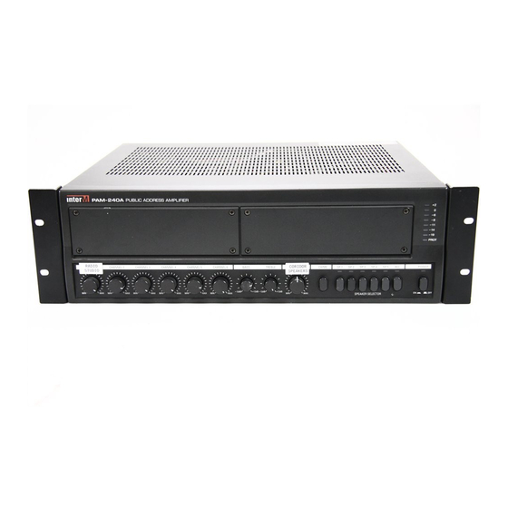
Front Panel
Module Bays
Identify panels for installing optional PAM modules via internal connectors.
Protection Indicator
Explains the LED that shows the status of the amplifier's protection circuitry.
Output Level Display
Describes the seven-segment LED meter indicating the amplifier's output level.
Channel 1-6 Volume
Details rotary controls for individual volume adjustments of Channels 1 through 6.
Tone Control
Explains bass and treble controls for adjusting low and high frequencies by ±12dB.
Master Volume
Identifies the rotary switch controlling the overall output volume of the amplifier.
Chime Button
Explains that pressing this switch activates the chime circuitry.
Speaker Selector
Describes switches used to select output to any combination of up to five individual speakers.
Power Switch
Details the switch that turns the unit on/off, indicated by the Power LED.
Rear Panel
Speaker Output Terminal Strip
Explains how to connect individual speakers and impedance matching requirements for 70V/100V operation.
Impedance Selector
Details the switch for selecting between high impedance (100V) and low impedance (70V) operation.
Antenna Connector (Optional)
Mentions the terminal for connecting an antenna with the optional AM/FM Tuner module.
EQ Controls
Describes three-band equalization controls for high, mid, and low frequencies, offering ±12dB adjustment.
Phantom Power Switch
Explains the switch for enabling/disabling +24V DC phantom power for condenser microphones.
Priority Switch
Describes switches that grant priority to Channels 1 and/or 2 over other inputs.
EM
Explains the EM switch for activating emergency broadcasting stored in VOICE IC.
EXT CHIME
Details activation of the four-tone chime circuitry via wired remote connection.
EXT MUTE
Explains muting of specific input channels via wired remote connection.
AC Power Input
Identifies the connector for a standard three-pin AC power cable.
Telephone Input Terminals
Describes terminals for connecting to a telephone system for paging purposes.
Music-on-Hold Terminals (PAM-T AM/FM Tuner Module Only)
Explains terminals used with the optional PAM-T module for supplying music-on-hold.
AC Fuse Holder
Locates the AC overload protection fuse and provides replacement guidance.
Remote Control Input
Details the 15-pin D-SUB connector for wired remote control of speaker zones and chime.
Preamp Output
Describes the line-level output for connecting to an external power amplifier.
Amp In
Explains the input for connecting an external mixer or preamp directly to the power amp.
Link Out
Identifies the line-level output for connecting to external mixdown decks or recording sources.
Link In
Describes the line-level input for connecting with an external mixer for expanded channels.
Channel Inputs 1-6
Details the balanced XLR connectors for microphone or low impedance signals.
Input Gain Controls
Explains continuous control knobs for input levels of the six channels to prevent distortion.
Connecting Speakers
Connecting High-Voltage Distributed Speaker Systems
Provides diagrams and guidance for connecting low-impedance (70V/100V) speaker systems in parallel.
Specifications
Amplifier Section
Lists key technical specifications like rated output power, frequency response, S/N, and input/output details.
General
Provides general specifications including power source, power consumption, weight, and dimensions.
Service
Procedures
Advises on troubleshooting operator error, external devices, and contacting warranty providers.
Schematic
States that a schematic is available by contacting the warranty provider.
Parts List
Mentions that a parts list is available by contacting the warranty provider.
Variations and Options
Variations
Notes that products are compatible with local AC power requirements.
Options
States that no optional items are available for this product.
Need help?
Do you have a question about the PAM-360A and is the answer not in the manual?
Questions and answers