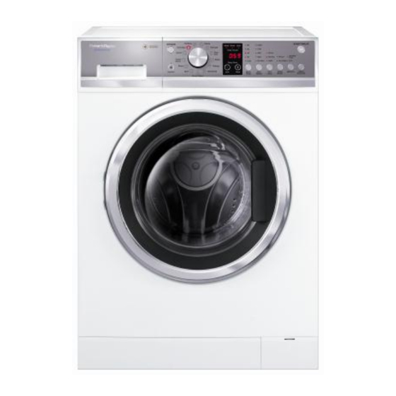
Summary of Contents for Fisher & Paykel customer care WH8560P1
- Page 1 Service Diagnostics Front Load Washer Models: WH8560P1 WH8560J1 WH8060P1 WH7560P1 WH7560J1 479645...
-
Page 2: Table Of Contents
479645 - OCTOBER 2014 CONTENTS SPECIFICATIONS ..................3 Electric Supply .................. 3 Capacity ....................3 Door Lock ................... 3 Heating Element ................3 NTC ..................... 3 Water Valves ..................3 Drain Pump ..................4 Wash Motor ..................4 Water Level Sensor ................4 MODEL/SIZE SETTING ................ -
Page 3: Specifications
479645 SPECIFICATIONS Electric Supply Voltage 220 – 240V Frequency 50Hz Power Consumption 2 kW Fuse Rating Capacity WH8560P1 8.5Kgs WH8560J1 8.5Kgs WH8060P1 8.0Kgs WH7560P1 7.5Kgs WH7560J1 7.5Kgs Door Lock Type Solenoid Activated With mechanical release 10% Resistance Terminal 2 & 3 Ω... -
Page 4: Drain Pump
479645 Drain Pump Voltage 220V – 240v AC 50Hz Total power 10% Resistance Ω Pump out rate 17litres/min Wash Motor Electronically commutated direct drive 3 Phase brushless DC motor Motor resistance: Aluminium Stator Per Winding Phase to Phase 10% ... -
Page 5: Model/Size Setting
479645 MODEL/SIZE SETTING When the control module is replaced, the correct model / size will need to be set for the machine. IMPORTANT: Do not set an 1100RPM machine to a 1400RPM setting, as it will cause significant damage to the drum, seal and bearings. 1 4 8 5 With the display Off press &... -
Page 6: Diagnostic Mode
479645 DIAGNOSTIC MODE Entering Diagnostic Mode With the display On, press & hold KEY LOCK and WASH TEMP for 3 Seconds. To enter the DIAGNOSTIC MODE: Turn the mains on at the supply and on at the control panel. Press and hold the KEYLOCK and WASHTEMP buttons together for at least 3 seconds, after which time two beeps will sound. -
Page 7: Self Test
479645 Self Test Select the SPIN cycle, then press the WASH TEMP button to activate the test program. 88:88 appears in the display and the door will lock. Once the door locks, • 77:77 appears in the display. Press the START/PAUSE button. 77:77 will remain in the display and the hot valve turns on. -
Page 8: Drum Rotation Test
479645 Cold Valve 2 Select the EVERYDAY cycle, then press the OPTIONS button to activate the cold valve 2. To deactivate the cold valve, press the OPTIONS button again. Drum Rotation Test Rotate Drum Clockwise Select the COTTON cycle, then press the WASH TEMP button to activate. To deactivate, press the WASH TEMP button again. -
Page 9: Diagnostics Levels
479645 Diagnostics Levels Diagnostics allows various information to be extracted from the machine, which can be used in both static, machine idle and machine dynamic running modes. There are a total of 15 different levels associated with the washer as listed in the accompanying table. - Page 10 479645 d 01: Last User Warning Cycle Count The cycle count at which the last user warning occurred displayed as1,000s, 100’s, 10’s & 1’s. E.g. For a cycle count of 1010 cycles 1 0 1 0 d 02: Last User Warning Wash Cycle Position The wash cycle position of the last user warning.
- Page 11 479645 d 05: Cycle Position at Last Fault The wash cycle position of the last fault. Output Displayed Cycle Position on Screen Agitation Rinse Spin d 06: Current Temperature (Degrees C) The temperature at the NTC Thermistor in d 07: Target Temperature The actual target temperature the machine is to obtain.
- Page 12 479645 d 09: Drum Speed The actual speed of the drum, displayed in Rev’s Per Minute. Once the machine has exceeded 999 RPM, the display output becomes alpha numeric. Letter A000 1000 B000 1100 C000 1200 D000 1300 E000 1400 E.g.
- Page 13 479645 d 10: Target Speed The target speed of the drum displayed in Rev’s Per Minute. d 11: Water Level The actual water level in the machine displayed as a frequency which decreases as the water level increases. d 12: Target Fill Level The target water level displayed as a frequency.
-
Page 14: Show Room Mode
479645 SHOW ROOM MODE This feature is designed for in-store demonstration purposes so that the machine can draw attention to itself and the different functions can be demonstrated. In this mode the machine cannot be started. press With the display On, &... -
Page 15: User Warnings
479645 USER WARNINGS There are a number of user warnings, which are generally caused by the user or poor installation. These warnings should be able to be corrected by the user. The machine signals user warnings by displaying a warning in plain text. Where multiple words are displayed, one word at a time with 1 second pause between changing from one word to the other along with a rippling set of 5 beeps which are repeated every 6 seconds. -
Page 16: Fault Codes
479645 FAULT CODES Before replacing any components, always check the harness and connections. Fault Code Short Description Reason door open Door detected as not closed. Door has been detected as not being closed 20 sec after program has been started. no tap Expected water level not Target water level has not been... - Page 17 479645 Err 75 Heater failure. The water failed to reach the selected wash temperature. Err 105 Comms Error. There is a communications error between the display and motor control module. Door lock not activating when Err 235 Door Locked instructed. ‘out of bal’...
-
Page 18: Connector Layout
479645 CONNECTOR LAYOUT CN14 Display Module Door Lock P171 P101 Motor Control Module... -
Page 19: Wiring Diagram
479645 WIRING DIAGRAM P171 Heater P324 P101 Component Resistance Heater CN1-4 to CN2-3 30 Ω CN14-3 to CN14-4 13 KΩ Motor Stator P171- 1to P171-2 28 Ω P171 -2 to P171-3 28 Ω P171-1 to P171-3 28 Ω Drain Pump CN1-5 to CN1-2 212 Ω...


Need help?
Do you have a question about the customer care WH8560P1 and is the answer not in the manual?
Questions and answers