Table of Contents

Related Manuals for MARELUX MX-A7IV


Summary of Contents for MARELUX MX-A7IV
- Page 1 MX-A7IV FOR SONY A7IV MIRRORLESS CAMERA Users’ Manual Please read this users’ manual carefully before starting to use the product, and use the product properly based on the thorough understanding of this users’ manual. https://marelux.co/...
-
Page 2: Important Notices
13. Marelux is not responsible for losing or damaging of user's photo, video or other form of user data in the camera or memory card. Marelux is not responsible for damages of user's camera, lens or other accessories when Marelux products are not properly used according to this user manual. - Page 3 O-Ring. 2. For maintenance of the Marelux O-Ring, only use the original lubricant supplied by Marelux. Any unauthorized usage of lubricant or chemical material from other brands on the O-Ring may cause malfunction or damage of the O-Ring and even lead to leakage to the housing.
-
Page 4: Part Names And Functions
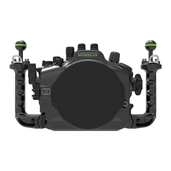
Part Names and Functions Front+Back Side View (10) (11) (12) (13) (14) (15) (17) (16) (18) (13)Down (1)C3 (7)Fiber Connector (14)Delete/C4 (2)MENU (8)OK (15)Ball Mount (3)Fn (9)Arrow Button (16)Handle (4)Alarm Light (10)Security Lock (17)Zoom Dial (5)Continuous shooting (11)DISP (18)Lens Release (6)SET (12)IOS (7)Fn... - Page 5 Part Names and Functions Up+Down Side View (20) Up+Down View (21) (19) (22) (23) (24) (26) (25) (19)MODE (25)Sacrificial Anode (20)Fiber Connector (26)1-20 UNC Screw Hole (21)ON/OFF (22)C2 (23)EV (24)Rear Dial...
- Page 6 Part Names and Functions Left+Right Side View (27) (28) (29) (31) (30) (32) (33) (34) (27)C1 (32)RED (28)Replay (33)Rear Dial (29)AF-ON (34)LOCKOPEN (30)AEL (31)Shutter...
-
Page 7: Install Camera
Install Camera... - Page 8 Install Camera Push the handle on the rightside of the housing mounting base to the right. Align the baseplate below the camera to the slot on the mounting base, and push the camera Lock the camera with baseplate onto the mounting base by pushing the handle to the left.
-
Page 9: Remove Camera
Remove Camera Push the handle to the right to release the camera from the mounting base. Pull the camera out of the mounting base. Push the handle back to the left to lock it. - Page 10 Open Housing Body Caution: 1. Please place the housing body on a flat surface before opening it. 2. Pull up the red knob of the vacuum valve to balance air pressure inside and out side the housing. Push the buttons of security locks on both Push the buttons of sides simultaneously...
- Page 11 Close Housing Body Caution: 1. Before closing the housing body, clean the O-Ring and put lubricant on it. 2. Make sure there is no foreign object accidentally staying between, and align the fringes of front and back cover Push both knobs of the Push both knobs of the security locks security locks...
- Page 12 Set up the moisture indicator and the leak detector alarm. Take out the insulation film of the battery. Press the battery gently till it touches the bottom. Press the red on/off button for one second to turn on the leak detector The indicator will blink twice in green (diagram 1) Then keep blinking in yellow (diagram 2) Diagram 1...
- Page 13 Mounting Ball Installation Diagram Ball Mount M5 Screw M5 Spring Washer M5 Washer Lift Ring Handle...
-
Page 14: Install O-Ring
Install O-Ring Caution: 1. Use finger or tool without sharp edge to take out the O-Ring from the housing. 2. Clean the O-Ring and the slot on the housing with a soft cloth, make sure there is no salt or other foreign objects remaining. - Page 15 Install Extension Ring Gently apply the supplied lubricant on the O-Ring and install it on the sealing groove. Set the safety lock of the extension ring in bulge state. (As shown in figure) Safety lock Align the dot sign on the extension ring to the bar sign on the dome port, then press the extension ring onto the dome port till they are fully attached.
- Page 16 Rotate the extension ring counterclockwise until the dot sign on the extension ring is aligned with the dot sign on the dome port. Turn the dome port to verify that the safety lock is locked. (As shown in Figure 2) Figure 2 Press the button on the extension ring lock and pull the knob outwards to open...
- Page 17 Hold the dome port assembled with the extension ring, align the bar sign of the extension ring with the dot sign of the housing, then press the extension ring onto the housing till they are fully attached. (As shown in Figure 3) Figure 3 Rotate the extension ring clockwise until the dot sign on the extension ring...
- Page 18 Push the extension ring lock of the housing inwards till it’s fully locked.
- Page 19 Disassembly Extension Ring Press the button on the extension ring lock and pull the knob outwards to open the lock. Rotate the extension ring counterclockwise until the bar sign on the extension ring aligns to the dot sign of the housing. (As shown in Figure 1) (1)...
- Page 20 Press down the safety lock inside the extension ring. Rotate the extension ring clockwise until the dot sign on the extension ring reached the bar sign of the dome port . (As shown in Figure 3) Figure 3...
- Page 21 Remove the dome port from the extension ring in the direction shown . (As shown in Figure 4) Figure 4...
- Page 22 Use Vacuum Valve Remove the cap from the vacuum valve by turning it counter clockwise. Put the nozzle of the pump on the vacuum valve, push and pull the handle of pump to extract air out of the housing until the vacuum indicator light turns green.
- Page 23 Release Vacuum Valve Remove the cap on the vacuum valve by turning it counter clock wise. Pull the red knob on the vacuum valve upwards. Till the vacuum indicator light turns red.
- Page 24 Install Gear How to use the rubber bars 1.There are slots for rubber bars on both the inner and outer side of the gear ring. Put one or two small rubber bars into each slot. 2.Adjust it till the contact between the lens and ring is neither too tight nor too loose. Put the plastic inner ring onto the lens first.
-
Page 25: Install Lens
Install Lens Push the wedge on the zoom dial forward. So the zoom dial and the gear parts inside the housing move sideway to leave enough space for lens to move through the front port of the housing. -
Page 26: Remove Lens
Remove Lens Push the wedge on the zoom dial forward. Press the lens release button and turn the lens to release it from the camera. Push the wedge on the zoom dial back to its original position. -
Page 27: Maintenance And Storage
Maintenance And Storage 1. After diving, make sure housing is locked and sealed, wash the housing body with fresh water. When immersed with fresh water, push each button few times, thus can help to let salt and sand go out. 3. -
Page 28: Warranty
6. Marelux is not responsible for and will not compensate any collateral damages or financial losses caused by using Marelux products, such as income or fees related to the users of Marelux products. Warranty is only provided to products sold inside the service territory of the distributor or reseller.
Need help?
Do you have a question about the MX-A7IV and is the answer not in the manual?
Questions and answers