Advertisement
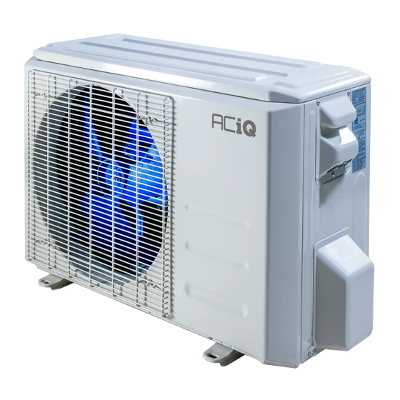
ACIQ EZ CONNECT HEAT PUMP SYSTEM
Owner's Manual &
Installation Manual
COVERS MODELS
ACIQ-12W-EZ115/ACIQ-12Z-EZ115
ACIQ-18W-EZ230/ACIQ-18Z-EZ230
ACIQ-24W-EZ230/ACIQ-24Z-EZ230
ACIQ-36W-EZ230/ACIQ-36Z-EZ230
IMPORTANT NOTICE:
Read this manual carefully before
installing or operating your new heat
pump unit. Make sure to save this
manual for future reference.
Advertisement

Summary of Contents for ACIQ ACIQ-12W-EZ115
- Page 1 ACIQ EZ CONNECT HEAT PUMP SYSTEM Owner’s Manual & Installation Manual COVERS MODELS ACIQ-12W-EZ115/ACIQ-12Z-EZ115 ACIQ-18W-EZ230/ACIQ-18Z-EZ230 ACIQ-24W-EZ230/ACIQ-24Z-EZ230 ACIQ-36W-EZ230/ACIQ-36Z-EZ230 IMPORTANT NOTICE: Read this manual carefully before installing or operating your new heat pump unit. Make sure to save this manual for future reference.
-
Page 2: Title Page
Instruction Manual ACIQ EZ - CONNECT HEAT PUMP SYSTEM IMPORTANT NOTE: Read this manual carefully before installing or operating your new heat pump unit. Make sure to save this manual for future reference. Please check the applicable models, technical ACIQ... -
Page 3: Table Of Contents
TABLE OF CONTENTS Title Page ................02 Safety Precautions.............03 Owners’ Manual Tools Required..............07 Getting Started..............08 Parts Included..............09 Installation Manual Installation................11 Electrical Connections............16 Diagram................17... -
Page 7: Tools Required
BASIC TOOLS LIST 1. 25 FT TAPE MEASURE 2. 2 FT LEVEL 3. UTILITY KNIFE 4. #2 PHILIPS SCREWDRIVER 5. 5MM ALLEN KEY 6. NEEDLE NOSE PLIERS 7. STANDARD SET OF DRILL BITS 8. CORDED OR CORDLESS DRILL 9. 3.5” HOLE SAW WITH ARBOR BIT 10. -
Page 8: Getting Started
THINGS TO CHECK BEFORE GETTING STARTED The circuit breaker is the appropriate size and type for the equipment being installed. Refer to the label on the outdoor unit for specifications. The circuit breaker is in the off position before attempting to install the system. -
Page 9: Parts Included
INCLUDED IN INDOOR SECTION BOX WILL BE A CONTENTS BAG Of2 MIXED PARTS THE PARTS BAG SHOULD INCLUDE THE FOLLOWING NetHome Plus Wi-Fi Adapter - Used for connecting the ACiQ EZ-Connect Heat Pump system to your Wi-Fi network. Hand held Remote Control - Used for temperature control of the ACiQ EZ-Connect Heat Pump system. - Page 10 OUTDOOR SECTION WHEN UNBOXING THE OUTDOOR SECTION, MAKE SURE THE TO CHECK FOR ANY PHYSICAL DAMAGE TO THE CONOENSER. IF THE CONDENSER SECTION IS DAMAGED, PLEASE STOP IMMEDIATELY AND GIVE US A CALL. IMPORTANT INCLUDED IN OUTDOOR SECTION BOX WILL BE A CONTENTS BAG OF MIXED PARTS.
-
Page 11: Installation
INSTALLATION Choose a location where the indoor unit will be installed. Pick a location that has at least 6'' of clearance from the top of the ceiling and 5'' from each side of the air handler. Make sure the installation location in not in direct sunlight, away from any obstacles that may block air circulation, and at least 3ft away from any other electronic devices. - Page 12 Bundle together the communication cable, refrigerant lineset connections, and drain tubing connection for preparing to pass it through the wall. Wrap the bundle together using the UV tape provided with the air handler. This will protect the bundle and make sure it passes easily through the wall sleeve.
- Page 13 LINESET CONNECTIONS Locate the refrigerant lineset provided with the outdoor unit. On a flat, level surface, carefully unroll the lineset to prepare and install at the factory connections for the indoor unit just passed through the wall. On the factory piping connections that were passed through the wall, remove the gray and blue caps so you can prepare to install the lineset.
- Page 14 Repeat step 18 at the outdoor condenser. line up the condenser connections to the lineset fittings. hand tighten the first few threads and use the adjustable wrenches to tighten down the rest. tighten unit all the threads can't be seen, and the fittings are bottomed out together.
- Page 15 LEAK CHECKING SYSTEM AND FINAL LINE SET PREPARATIONS Using a spray bottle, prepare a solution of soapy water to leak check the fittings. The more suds in the solution, the easier any leaks will be to find. Dish soap and water works well for this process. Spray down all the refrigerant lineset connections and fittings with the soapy solution.
-
Page 16: Electrical Connections
ELECTRICAL CONNECTIONS IMPORTANT - PLEASE DOUBLE CHECK AND MAKE SURE YOU HAVE THE CORRECT POWER SOURCE BEING USED FOR THE SYSTEM PURCHASED. FOR THE 12K BTU SYSTEM, IT WILL REQUIRE A SINGLE POLE 15-AMP BREAKER, 115 VOLTS FOR THE 18K BTU SYSTEM, IT WILL REQUIRE A DOUBLE POLE 20-AMP BREAKER, 240 VOLTS FOR THE 24K BTlcJ SYSTEM, IT WILL REQUIRE A DOUBLE POLE 30-AMP BREAKER, 240 VOLTS... -
Page 17: Diagram
DIAGRAM FOR PREVIOUS PAGE...


Need help?
Do you have a question about the ACIQ-12W-EZ115 and is the answer not in the manual?
Questions and answers