Table of Contents
Advertisement
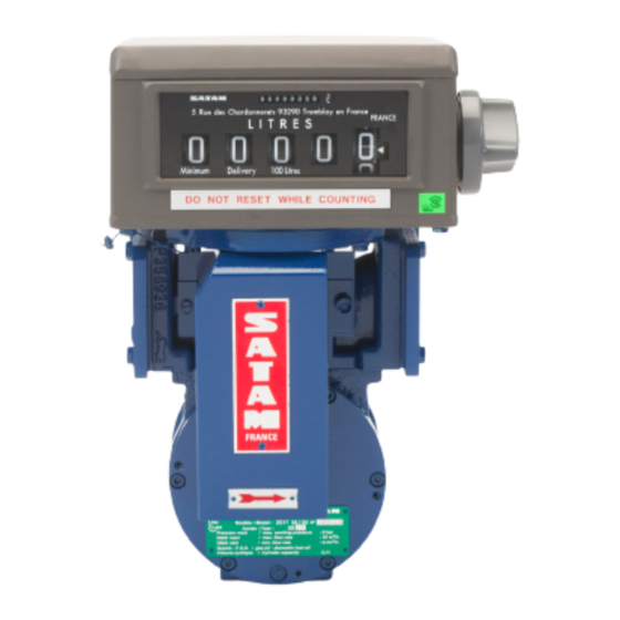
MEASURING CHAMBERS – ZC 17-24
Description – Installation – Operation – Servicing
This document consists of
And can't be transmitted to someone also with out prior authorisation
In conformity with the European directive 94/9/CE-ATEX
SATAM
Usine de Falaise – Avenue de Verdun – B.P. 129 – 14700 FALAISE – France
Tél. : +33 (0)2 31 41 41 41
Fax : +33 (0)2 31 40 75 61
SIRET 495 233 124 000 17
CODE APE 2813 Z
and ZC 17-48 METERS
U508113-e– Révision 4 – 29 March 2012
This document is the property of SATAM
SATAM may modify this document without prior notice
--
16
pages, (including the flyleaf)
Siège Social : Paris Nord II – Bât. Le Gauguin – 47, allée des Impressionnistes
B.P. 85012 – Villepinte – 95931 Roissy C.D.G. Cedex - France
Tél. : +33 (0)1 48 63 02 11
Fax : +33 (0)1 49 38 41 01
SA au capital de 6 037 000 € – RCS Bobigny B 495 233 124
SIRET 495 233 124 000 17 – Code APE 2813 Z – N° TVA : FR 48 495 233 124
Advertisement
Table of Contents

Related Manuals for SATAM ZC 17-24


Summary of Contents for SATAM ZC 17-24
- Page 1 (including the flyleaf) This document is the property of SATAM And can’t be transmitted to someone also with out prior authorisation SATAM may modify this document without prior notice In conformity with the European directive 94/9/CE-ATEX SATAM Siège Social : Paris Nord II – Bât. Le Gauguin – 47, allée des Impressionnistes Usine de Falaise –...
-
Page 2: Table Of Contents
MEASURING CHAMBERS – ZC 17-24 and ZC 17-48 METERS SUMMARY GENERAL ..............................3 RECEPTION..............................3 OPERATING PRINCIPLE ..........................3 COMPONENTS.............................4 DESCRIPTION..............................6 5.1. Blade-type positive displacement measuring chamber ................6 5.2. A manifold..............................7 5.3. A transmission system ..........................8 5.4. AB 35 Calibrating mechanism .........................9 5.5. -
Page 3: General
1. General This chapter contains information relating to the reception and assembly of the ZC 17-24 and ZC 17- 48 METERS. 2. Reception The meters are packed in cardboard packing designed for and adapted to protect the meters during transport. -
Page 4: Components
Cell with the shape in the axis of the body Cell with the shape in 45 ° of the axis of the body 4. Components After removing the meter from its packaging, you will find it is composed of the following elements : Standard Meter LIT RE LIT RE... - Page 5 A wide range of accessories LIT RE LIT RE M /h - Ticket printer (1) : accumulative model or 0-start model - A preset (2) with main valve type XAD 39 (3) with mechanical actuator or XAD 54 with pneumatic actuator - A 3-way-Valve (4) equipped with its valve box (5) - A rate of flow indicator reading in l/min, m3/h.(6) Edition du 29/03/12...
-
Page 6: Description
5. Description 5.1. Blade-type positive displacement measuring chamber Measuring apparatus with fixed lids Centre o Measuring apparatus with centered lids The measuring chamber consists of : a body (1) in ni-resist cast iron or aluminum IN AC-42200 S T6 (HAVE 7G 06 Y23), made up of 2 cylindrical parts (2) and (3) of different radii, connected via curves in such a way that the sum of the distances from center point 0 to two points opposite each other on the stator is constant. -
Page 7: A Manifold
5.2. A manifold Position 1 Position 2 An aluminium manifold is mounted on the measuring chamber. The position of the gears differs according to the position of the register. Edition du 29/03/12 7/16 U508113-e Révision 4... -
Page 8: A Transmission System
5.3. A transmission system for mechanical indicator The transmission system forms the link between the measuring chamber and the calibrating mechanism. Two different types of system are available : standard system consisting of : - a housing (1) - a drive axle (2) - a measuring chamber outlet gear (3) - a transmission(4) a system designed to receive a "Instantaneous Flow Rate"... -
Page 9: Ab 35 Calibrating Mechanism
5.4. AB 35 Calibrating mechanism for mechanical indicator The AB 35 calibrating mechanism is located at the outlet of the transmission device. The movement of the measuring chamber drives the transmission device gear via the endless screw. At the end of the transmission device, a drive shaft links to the AB 35 calibrating mechanism. -
Page 10: Preset With Xad 39 Mechanical Preset Valve
5.5. Preset with XAD 39 mechanical Preset valve A cam assembled on the lower part of the preset controls a shaft which opens or closes the preset valve . The Preset valve consists of the following elements : An outer casing in aluminium (1) A moving needle (2) A mobile part consisting of a piston (3), a gasket (4) which slides within the chamber A spring (5) maintaining the moving part on its seat (6) -
Page 11: Installation
Pull the control lever towards yourself 7.2. Checking low flow initiation For a ZC 17-24 or a 48 meter, low flow is initiated at approximately 30 litres from the end of delivery (transfer from high to low flow at 30 litres from end of loading). -
Page 12: Ways Valve Operation
7.3. 3 ways valve operation 1. Insert a ticket in the ticket printer 2. Choose the outlet pipe required (either via the front (B) or the back (A) of the valve) by using the lever (1). a) lightly pull the lever (1) and position it in relation to the outlet pipe required (position A or B) and put the lever (2) in a open position 0. -
Page 13: Metrological Inspection Measuring Chamber
8. Metrological Inspection Measuring Chamber 8.1. General Current DIRRECTE and LNE (Weights and Measures) legislation require : . Metrological inspection of meter at operation start-up . Subsequent yearly inspections. If during gauging the meter is found to be outside the accepted error, it is possible to re-calibrate the meter using the AB 35 calibrating mechanism. - Page 14 C. ADJUSTMENT OPERATION OF AB 35 1- Unseal and remove the cover (1) 2- Unscrew the two screws (3) 3- Slide the cover down. 4- Carry out adjustment as described above (§B) 5- Check adjustment by carrying out a new gauging test. 6- Put the cover back in place and tighten the screws.
-
Page 15: Periodic Servicing
9. Periodic servicing 9.1. General Periodic maintenance is required at least once a year. Service operations must be carried out by a Company approved by Weights & Measures. 9.2. Monthly Periodic Inspections 9.2.1. Strainer Baskets The strainers installed upstream of the meter should be inspected. N.B Filtration for Gasoline/premium/Jet : 200microns Filtration for Gas oil, Diesel Oil, Fuel Oil : 450 microns 9.2.2. -
Page 16: Meter Head
AB35 Entry AB35 Take care about the alignment between axle 1 and the AB 35 entry 9.4. Meter Head See the Installation and Operation Manual. 9.5. REMARK VERY IMPORTANT We strongly advise against the use of a high pressure water jet to clean the measuring unit, as this could seriously damage the metering unit.
Need help?
Do you have a question about the ZC 17-24 and is the answer not in the manual?
Questions and answers
هل يمكنني الحصول على قطع غيار AB 35 عداد satam zc 1724