
Related Manuals for SATAM ZCM17


Summary of Contents for SATAM ZCM17
- Page 1 MASTER METER Description, Operation, Maintenance 1/19 U518156‐en‐REV0 02/2018 Edition ...
- Page 2 About This Manual This document contains 19 pages, including the front page. This document is the property of SATAM. It may not be distributed to third parties without prior authorization. SATAM reserves the right to modify this document without prior notification. This document complies with the current European ATEX Directive. Revision history 2018/02/09 Rev 0 Creation Support and Contact Information Service department Avenue de Verdun CS60129 Tel: +33 (0)9 80 80 04 02 Email : service@satam.eu Manufacturing facility Avenue de Verdun CS 60129 ...
-
Page 3: Table Of Contents
Table of Contents 1. Functionalities .......................... 4 2. General arrangement of ZCM17 ..................... 4 A. Version with electronic register .................... 4 B. Version with mechanical register .................... 5 3. Main components of ZCM17 master meter .................. 6 A. Positive displacement meter ZC17 .................... 6 B. Electronic register EQUALIS S ...................... 7 C. Mechanical register ........................ 8 D. Rate of flow indicator ........................ 9 4. Narrative Description ........................ 10 5. Periodic Servicing .......................... 10 6. Cleaning ............................ 10 7. Meter Calibration Inspection – Weight and Measures .............. 11 A. Adjustment Procedure with transmitter AB 21 ................. 11 ... -
Page 4: Functionalities
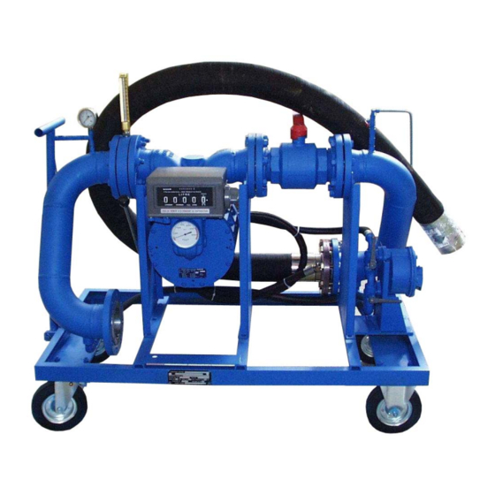
1. Functionalities Satam master meters model ZCM17 are dedicated to periodic calibration of custody transfer measuring equipment for fuels and petroleum products. ZCM 17 is a working standard that can be used regularly to check and calibrate measuring instruments or measuring systems. 2. General arrangement of ZCM17 A. Version with electronic register Electronic Release register valve Pressure gauge Connecting Release pipe valve Drainage pump Connection to PD meter flexible hose 4/19 U518156‐en‐REV0 02/2018 Edition ... -
Page 5: Version With Mechanical Register
B. Version with mechanical register * : optional supply Mechanical Temperature Isolating register probe (*) valve (*) Release Pressure valve gauge Connecting Release pipe valve Drainage pump ... -
Page 6: Main Components Of Zcm17 Master Meter
3. Main components of ZCM17 master meter Satam ZCM17 master meter consists of the following components A. Positive displacement meter ZC17 The measuring chamber of Satam ZC17 is composed of ‐ A body (1) made up of 2 cylindrical parts (2) and (3) of different radii, connected via curves in such a way that the sum of the distances from centre point O to two points opposite each other on the stator is constant. ‐ A moving part (4) composed of a rotor turning on stainless steel ball bearings (6), carbon blades (7) linked to each other by rods (8) and 2 steel covers (9) and (10). Measuring principle The product enters the measuring chamber following the direction of the arrow. The rotor and blades assembly (1‐2) is set in motion by the pressure of the liquid on blades. A certain amount of liquid (3) is held between 2 blades and then directed to the discharge manifold. The volume of liquid measured at each rotation is therefore equal to 4 times the measured quantity (3). The smooth curves the meter pieces provide a steady, non‐fluctuating flow resulting in low head loss. The rotation of the rotor is transmitted mechanically either to a pulses transmitter in case of a device fitted with electronic register or to an adjusting mechanism is case of a device fitted with mechanical register. 6/19 U518156‐en‐REV0 02/2018 Edition ... -
Page 7: Electronic Register Equalis S
For complete information about ZC17 operation please refer to following technical manuals : Reference Technical manual U508131 Description, installation, operation, servicing for ZC17‐24 and ZC17‐48 U508334 Description, installation, operation, servicing for ZC17‐80; ZC17‐150, ZC17‐250 and ZC17‐330 B. Electronic register EQUALIS S The EQUALIS S Field Batch Controller depot version is an intelligent electronic calculator/indicator, controlled by several embedded microprocessors, designed for efficient management of fluid measurement. It carries out the calculation, display and management functions, essential to product loading or unloading. EQUALIS is designed to be used in an explosive atmosphere, with different protection modes, in accordance with directive ATEX 94/9/CE. ... -
Page 8: Mechanical Register
The main features of the EQUALIS S flow computer are the following: Graphic display: Any information necessary required to use the EQUALIS S is displayed on a single screen, in a way that is user‐friendly and interactive. Dust and water resistant: EQUALIS has been developed and manufactured in such a way as to make it resistant to the risks of everyday use and the elements. Adjustable meter curve: The EQUALIS has a parameter used to correct the curve by reducing the counter to 0 ‰ measurement error at operation flow rate. It also provides the possibility to linearize ... -
Page 9: Rate Of Flow Indicator
D. Rate of flow indicator Each ZCM17 is able to display the flow rate in L/min or in m3/h. When fitted with a mechanical register, the rate of flow indicator is an external module located at the bottom of the register. The physical unit of the flow must be define at the order of the master meter. When fitted with a electronic register, the flow rate value is directly displayed on the register without the need of any ... -
Page 10: Narrative Description
4. Narrative Description ‐ Connect ZCM17 with hose between the metering system to be tested and the receiving tank ‐ Start a delivery to fill the ZCM17 up to the transfer point ‐ Reset the mechanical head / Put the Equalis S in delivery mode ‐ Start delivery with a preset volume ‐ Compare the volume displayed by the master meter with the one displayed by the meter to be tested ‐ Adjust the meter correction coefficient ‐ Start a new delivery to confirm the correction ‐ Use the drainage hand pump to empty the ZCM17 to limit pollution when disconnecting or testing with a new fluid ‐ Disconnect the ZCM17 hose 5. Periodic Servicing As a general rule, a periodic maintenance of at least once a year is recommended. Service operations must be carried out by a Weights & Measures approved Company. 6. Cleaning We strongly advise against the use of a high pressure water jet to clean the measuring unit, as this could seriously damage the metering unit. ... -
Page 11: Meter Calibration Inspection - Weight And Measures
7. Meter Calibration Inspection – Weight and Measures Current French legislation stipulates: ‐ Metrological inspection of the meter at operation start‐up. ‐ Thereafter, annual inspections. A. Adjustment Procedure with transmitter AB 21 ‐ Unseal and remove cover (A) ‐ Move roller (5) by turning screw (6) using spanner "C" until the roller hole is aligned with the 2 holes on the support (15) ‐ Insert pin (B) as shown on the diagram. ‐ Turn the screw right (clockwise) to increase the quantity of product in the gauge. ‐ Turn the screw left (anticlockwise) to decrease the quantity of product in the gauge. ‐ One turn of the screw (6) = Correction of 1‰ Pin B = SATAM ref. 359809 Spanner C = SATAM ref. 359810 CAUTION : Do not omit to remove Pin "B" after adjustment. ... -
Page 12: Adjustment Procedure With Equalis S
B. Adjustment Procedure with EQUALIS S 12/19 U518156‐en‐REV0 02/2018 Edition ... - Page 13 13/19 U518156‐en‐REV0 02/2018 Edition ...
- Page 14 14/19 U518156‐en‐REV0 02/2018 Edition ...
- Page 15 15/19 U518156‐en‐REV0 02/2018 Edition ...
-
Page 16: Technical Data Of Zcm17 Mastermeter
2;4 / 24 40 / 400 10.5 / 105 ZCM17-48 4.8 / 48 80 / 800 21 / 210 ZCM17 - 80 8 / 80 133 / 1333 36 / 360 ZCM17-150 15 / 150 250 / 2500 66 / 660... -
Page 17: Technical Data: Zcm With Electronic Register
3mL / Loose type flanges ASA 150lbs, TODO type couplings, CAMLOCK type couplings Flexible hoses / Connections Model Nominal size ZCM17-24 DN50 / 2’’ ZCM17-48 DN50 / 2’’ ZCM17 - 80 DN80 / 3’’ ZCM17-150 DN100 / 4’’ ZCM17-250 DN150 / 6’’ ZCM17-330 DN200 / 8’’... - Page 18 Measuring chamber Displacement element type Sliding vanes flowmeter Cyclic volume Model ZCM17-24 ZCM17-48 0.21 ZCM17 - 80 2.27 ZCM17-150 4.54 1.12 ZCM17-250 6.82 ZCM17-330 9.09 Blades / Blades connection rods Graphite / Stainless steel Rotor / Bearings Aluminum (EN AC-42100) / Stainless steel (EN 1.4301)
-
Page 19: Dimensions And Weight (Trolley Version)
Hoses for process connection are not shown on this drawing. Dimensions (mm) ZCM17-24 ZCM17-48 ZCM17-80 ZCM17-150 ZCM17-250 ZCM17-330 1100 1100 1400 Please 1100 1100 1199 1250 1200 contact 1050...
Need help?
Do you have a question about the ZCM17 and is the answer not in the manual?
Questions and answers