Table of Contents
Advertisement
Quick Links
DESCRIPTION - INSTALLATION - OPERATION -
This document consists of
And may not transmitted to third parties without prior authorisation
SATAM may modify this document without prior authorisation
SATAM
Usine de Falaise – Avenue de Verdun – B.P. 129 – 14700 FALAISE – France
Tél. : +33 (0)2 31 41 41 41
Fax : +33 (0)2 31 40 75 61
SIRET 495 233 124 000 17
CODE APE 2813 Z
SERIES 7888 METER PRINTER
MANUAL
SERVICING
U508219-e – Revision 2 – 25 February 2009
This document is the property of SATAM
CONFORME à la directive européenne 94/9/CE – ATEX
In conformity with the European directive 94/9/CE-ATEX
18
pages, including the flyleaf
Siège Social : Paris Nord II – 5, rue des Chardonnerets
B.P. 85012 – Tremblay- en-France – 95931 Roissy C.D.G. Cedex - France
Tél. : +33 (0)1 49 90 77 00
Fax : +33 (0)1 49 90 77 99
SA au capital de 6 037 000 € – RCS Bobigny B 495 233 124
SIRET 495 233 124 000 17 – Code APE 2813 Z – N° TVA : FR 48 495 233 124
Advertisement
Table of Contents
Troubleshooting

Related Manuals for SATAM 7888 Series


Summary of Contents for SATAM 7888 Series
- Page 1 This document is the property of SATAM And may not transmitted to third parties without prior authorisation SATAM may modify this document without prior authorisation CONFORME à la directive européenne 94/9/CE – ATEX In conformity with the European directive 94/9/CE-ATEX SATAM Siège Social : Paris Nord II –...
-
Page 2: Table Of Contents
Summary SECTION 1. INTRODUCTION.......................... 3 A. GENERAL ..............................3 SECTION 2. DESCRIPTION ..........................4 A. OPERATION OF ZERO START PRINTER....................4 B. OPERATION OF ACCUMULATIVE PRINTER..................4 SECTION 3. PRINTER REMOVAL AND INSTALLATION ................ 6 A. REMOVAL..............................6 B. INSTALLATION............................6 SECTION 4. -
Page 3: Section 1. Introduction
SECTION 1. INTRODUCTION A. GENERAL These instructions are for servicing the Series 7888 Printer Registers. Every Meter Register is thoroughly tested at the meter factory when installed on the meter. However, like any precision mechanism, it requires periodic care to ensure maximum service. This manual is for use in areas where factory rebuilding facilities and adequate exchange stocks are not readily accessible. -
Page 4: Section 2. Description
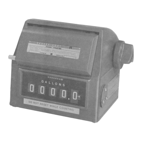
Figure 1. Series 7888 Meter Printer Mounted on Series 7887 Meter Register SECTION 2. DESCRIPTION A. OPERATION OF ZERO START PRINTER. 3. Printing. ln printing operation, a ticket is inserted into the slot of the ticket tray unit it The Series 788800 Meter Printer (Zero Start) bottoms on the internal stop. - Page 5 Figure 2. Drive Train ( Zero Start) Figure 4. Drive Train ( Accumulative) Figure 3. Reset Train (Zero Start) Figure 5. Tray Actuating Train( accumulative) Edition du 25/02/09 U508219-e Revision : 2...
-
Page 6: Section 3. Printer Removal And Installation
1. Drive. The shaft, Figure 4, on the bottom of 2. Install printer knob and shaft extension on the printer is driven by a bevel gear from a printer and turn it until tray is in the outward meter register or other equipment. -
Page 7: Section 4. Cleaning And Lubricating
SECTION 4. CLEANING AND LUBRICATING A. GENERAL C. RECOMMENDED LUBRICATION. Although the printer is adjusted and lubricated Note: Chemlube and Vischem products are when manufactured, it does require periodic manufactured by Ultrachem Inc. cleaning and lubrication to give maximum service. Oil: Chemlube 201 or equivalent with a Judgement of the intervals at which the printer temperature range of -650 to +275°... -
Page 8: Lubrication Points
Figure 8. Lubrication Points -Zero Start Printer D. LUBRICATION POINTS (Figures 7 to 10). 1. Apply recommended or equivalent oil to 2. Apply recommended or equivalent grease to bearing surfaces of aIl shafts, studs, and bearing and mating surfaces of aIl bevel gears, bosses on which parts move or rotate. -
Page 9: Section 5. Troubleshooting
Figure 10. Lubrication Points - Accumulative Printer SECTION 5. TROUBLESHOOTING A. GENERAL CHECKS. (Figures 11 through 15). If the reason for the trouble is unknown, it is a. Tray moves forward to "Print ln" position and necessary to examine the printer to locate and seal pin pierces ticket (wheels reset to zero on replace malfunctioning parts. - Page 10 6. Check print wheel end play for 0.020 to 11. Check the tray support rods to be certain 0.025 inches. they are free and secured in place by four clips. 7. Turn the printer so the printing arm faces you. Check the springs to see that they are 12.
- Page 11 Reset Ticket Gear Piercing Stop Seal Pin Arm and Screw Actuating Printing Spring Ticket Tray Ticket Tray Support Rod Tray Actuating Cam and Reset Gear Print wheel Group Ticket Tray Aligning Support Rod Gear Group Printing Arm Spring Figure 12. Parts Identification Figure 13.
-
Page 12: Troubleshooting
B. TROUBLESHOOTING. Tables 1 and 2 are used to assist in locating 2. To adjust the lateral position of the ticket, problems and making minor repairs and remove the two ticket shield screws and shield. corrections in the field. ln some problems, Move the guides in notches to position the similar defects can be produced by several ticket properly, then replace shield and screws. -
Page 13: Sales Number Advancing Mechanism Inspection
D. SALES NUMBER ADVANCING MECHANISM INSPECTION. 1. Sales number advancing mechanism, Figure 17, is tripped when printing occurs. The movement of the sale advance wheel starts immediately with rotation of the input shaft and completes transfer within 1/4 of a revolution. If the sales number on the right-hand wheel does not align properly with the other wheel, it must be adjusted. -
Page 14: Right-Hand Wheel Inching Mechanism Adjustment
E. RIGHT-HAND WHEEL INCHING MECHANISM ADJUSTMENT. 1. Adjustment of the inching of the printer's right-hand wheel is accomplished by turning the adjusting set screw, Figure 18. Turning screw clockwise, the inching occurs at a higher number and counterclockwise at lower inching numbers. -
Page 15: Wheel Removal
B. WHEEL REMOVAL. 8. Place washer on wheel shaft (outside of 1. Remove ticket tray (See Paragraph A). frame) and install retaining E-ring. 2. Remove retaining ring and washer from For AccumuIative Printers wheel shaft (left side). 3. Remove wheel aligning spring from wheel 9. -
Page 16: Reset Gears Replacement And Timing Of Printer
4. Install E-ring and place two washers on 9. Hold tray in rear position and install reset shaft outside the frame, small diameter washer gear on stud. next to frame. Note: Timing mark on small reset drive gear 5. Place and pin printing cam on shaft, keeping must mesh between the two timing marks on cam cliff in upper rear position with head of the large reset gear. -
Page 17: Section 7. Installation Instructions
SECTION 7. INSTALLATION INSTRUCTIONS FOR KITS 312020-357, -423, -675, AND -893 A. INTRODUCTION. 7. Manually reset the meter register character wheels to zero and set the unit aside. Each kit contains aIl parts necessary for installation of a Series 7888 Ticket Printer on a 8. -
Page 18: Operational Check
11. Install the plastic security cap on the end 15. Insert shaft extension with washers thru of the meter register reset idler gear shaft. hole in cover and engage the end of knob shaft. 12. Install the meter register /ticket printer assembly in the case and secure with the 16.
Need help?
Do you have a question about the 7888 Series and is the answer not in the manual?
Questions and answers