Table of Contents
Advertisement
Quick Links
Description – Installation – Operation –
This document consists of
And may not be transmitted to third parties without prior authorisation
In conformity with the European directive 94/9/CE-ATEX
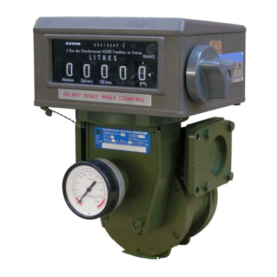
SATAM
Usine de Falaise – Avenue de Verdun – B.P. 129 – 14700 FALAISE – France
Tél. : +33 (0)2 31 41 41 41
Fax : +33 (0)2 31 40 75 61
SIRET 495 233 124 000 17
CODE APE 2813 Z
BULKMETER ZC 17-12
Servicing
U514986-e – Revision 4 – 25 April 2012
This document is the property of SATAM
SATAM may modify this document without prior notice
15
pages, (including the flyleaf)
Siège Social : Paris Nord II – Bât. Le Gauguin – 47, allée des Impressionnistes
B.P. 85012 – Villepinte – 95931 Roissy C.D.G. Cedex - France
Tél. : +33 (0)1 48 63 02 11
Fax : +33 (0)1 49 38 41 01
SA au capital de 6 037 000 € – RCS Bobigny B 495 233 124
SIRET 495 233 124 000 17 – Code APE 2813 Z – N° TVA : FR 48 495 233 124
Advertisement
Table of Contents

Related Manuals for SATAM ZC 17


Summary of Contents for SATAM ZC 17
- Page 1 (including the flyleaf) This document is the property of SATAM And may not be transmitted to third parties without prior authorisation SATAM may modify this document without prior notice In conformity with the European directive 94/9/CE-ATEX SATAM Siège Social : Paris Nord II – Bât. Le Gauguin – 47, allée des Impressionnistes Usine de Falaise –...
-
Page 2: Table Of Contents
BULKMETER ZC 17-12 Summary 1. COMPONENTS ........................ 3 1.1. Constitution..........................3 The electronic meter consists of following elements:................4 1.2. Operating principle ........................5 1.3. Blade-type positive displacement measurement chamber ............6 1.4. Transmission device AB40....................... 7 1.5. AB35 adjustment device......................8 1.6. -
Page 3: Components
1. Components 1.1. Constitution The mechanical meter consists of following elements: - A positive displacement measuring chamber type MA 21 (1). - A transmission system (2) AB40 comprising: - A calibrating mechanism model AB35 (3). - A meter head (4) - An accumulative ticket printer with a reset can be linked to the register. -
Page 4: The Electronic Meter Consists Of Following Elements
The electronic meter consists of following elements: - A positive displacement measuring chamber type MA 21 (1). - Transmitter(Issuer) of impulses AC 30 (2) - Electronic computer MPC (3) Printed on 26/04/12 4/15 U514986-e Revision 4... -
Page 5: Operating Principle
1.2. Operating principle Meter with inlet on left The liquid enters the metering unit in the direction indicated by the arrows (A). The rotor assembly is set in motion under the pressure of the liquid on the blades (3). A certain amount of liquid (4) is captured between two consecutive blades, and measured on the part of the circular way corresponding to the biggest of the 2 radii of the stator, and then pushed towards the outlet manifold (B). -
Page 6: Blade-Type Positive Displacement Measurement Chamber
1.3. Blade-type positive displacement measurement chamber Centre O The measuring chamber consists of: - An aluminium body (1) made up of 2 cylindrical parts (2) and (3) of different radii, connected via curves in such a way that the sum of the distances from center point O to two points opposite each other on the stator is constant. -
Page 7: Transmission Device Ab40
1.4. Transmission device AB40 The transmission device, including the adjustment device AB35, forms the links between the measurement chamber and the mechanical indicating device. It consists of : - A housing (1) - A adjustment device AB35 (2) - A drive shaft (3) - Conical gears (4 &... -
Page 8: Ab35 Adjustment Device
1.5. AB35 adjustment device Using the AB35 calibrating mechanism it is possible to vary the speed of rotation between the inlet shaft (1) and the outlet shaft (2) in order to adjust the precision of the meter. The AB35 calibrating mechanism is located at the outlet of the transmission device. The movement of the measuring chamber drives the transmission device gear via the endless screw. -
Page 9: Preset With Xad 39 Mechanical Preset Valve
1.6. Preset with XAD 39 mechanical Preset valve A cam assembled on the lower part of the preset controls a shaft which opens or closes the preset valve . The Preset valve consists of the following elements : An outer casing in aluminium (1) A moving needle (2) A mobile part consisting of a piston (3), a gasket (4) which slides within the chamber A spring (5) maintaining the moving part on its seat (6) -
Page 10: Installation
Pull the control lever towards yourself 4.2. Checking low flow initiation For a ZC 17-24 or a 48 meter, low flow is initiated at approximately 30 litres from the end of delivery (transfer from high to low flow at 30 litres from end of loading). -
Page 11: Ways Valve Operation
Position Petit Débit 45° Cran d’ornement Réglage du petit débit par rotation du galet excentrique avec une clé extra plate de 19 et une clé plate de 10 4.3. 3 ways valve operation 1. Insert a ticket in the ticket printer 2. -
Page 12: Metrological Check - Adjustment Operation
5. Metrological check - Adjustment operation 5.1. Metrological check Current DIRRECTE and LNE (Weights and Measures) legislation require : . Metrological inspection of meter at operation start-up . Subsequent yearly inspections. If during gauging the meter is found to be outside the accepted error, it is possible to re-calibrate the meter using the AB 35 calibrating mechanism. - Page 13 5 - Check adjustment by carrying out a new gauging test 6 - Put the cover back in place and tighten the screws. 7 - Re-seal C - PRINCIPLE OF ADJUSTMENT Reminder : 1 notch of the calibration screw (3) = 0.25‰ in whatever direction adjustment is made. 1 - Note the position of the calibrating screw.
-
Page 14: Servicing
6.3.1. Measurement chamber MA21-12 The actual measuring chamber itself does not require preventive maintenance. Any intervention necessary must be carried out by a repairer approved by SATAM with test equipment approved for basic inspections of the meter. 6.3.2. Mechanical indicating device See the Installation and Operation Manual. -
Page 15: Transmission Device Ab40
6.3.3. Transmission device AB40 The worm screw and gear (1 & 2) : - Check clearance - Clean and grease Bearings (4 & 5) on shaft (3) : - Check wear - Clean and grease In the upper part of the AB40 : - Check the rings and the drive gear shaft leading to the mechanical indicating device - Clean and grease the drive gears assembly N.B : The AB35 adjustment device does not require preventive maintenance.
Need help?
Do you have a question about the ZC 17 and is the answer not in the manual?
Questions and answers