Table of Contents
Advertisement
Quick Links
MECHANICAL REGISTER SERIE 7887
DESCRIPTION - INSTALLATION – OPERATION -
This document consists of
And may not transmitted to third parties without prior authorisation
SATAM may modify this document without prior authorisation
SATAM
Usine de Falaise – Avenue de Verdun – B.P. 129 – 14700 FALAISE – France
Tél. : +33 (0)2 31 41 41 41
Fax : +33 (0)2 31 40 75 61
SIRET 495 233 124 000 17
CODE APE 2813 Z
MANUAL
SERVICING
U508218-e – Revision 02 – 24 February 2009
This document is the property of SATAM
In conformity with the European directive 94/9/CE-ATEX
17
pages, including the flyleaf
Siège Social : Paris Nord II – 5, rue des Chardonnerets
B.P. 85012 – Tremblay- en-France – 95931 Roissy C.D.G. Cedex - France
Tél. : +33 (0)1 49 90 77 00
Fax : +33 (0)1 49 90 77 99
SA au capital de 6 037 000 € – RCS Bobigny B 495 233 124
SIRET 495 233 124 000 17 – Code APE 2813 Z – N° TVA : FR 48 495 233 124
Advertisement
Table of Contents

Related Manuals for SATAM 7887 Series


Summary of Contents for SATAM 7887 Series
- Page 1 This document is the property of SATAM And may not transmitted to third parties without prior authorisation SATAM may modify this document without prior authorisation In conformity with the European directive 94/9/CE-ATEX SATAM Siège Social : Paris Nord II – 5, rue des Chardonnerets Usine de Falaise –...
-
Page 2: Table Of Contents
Summary 1. INTRODUCTION .............................. 3 1.1. GENERAL .............................. 3 2. SERIES 7887 DESCRIPTION ........................... 4 2.1. GENERAL..............................4 3. PERIODIC INSPECTION ..........................6 3.1. GENERAL..............................6 3.2. DISASSEMBLY PRIOR TO CLEANING....................6 3.3. CLEANING..............................6 3.4. INSPECTION.............................. 6 3.6. -
Page 3: Introduction
1. INTRODUCTION 1.1. GENERAL These instructions are for servicing the Series 7887 Meter Registers. Every Meter Register is thoroughly tested at the meter factory when installed on the meter. However, like any precision mechanism, it requires periodic care to ensure maximum service. This manual is for use in areas where factory rebuilding facilities and adequate exchange stocks are not readily accessible. -
Page 4: Series 7887 Description
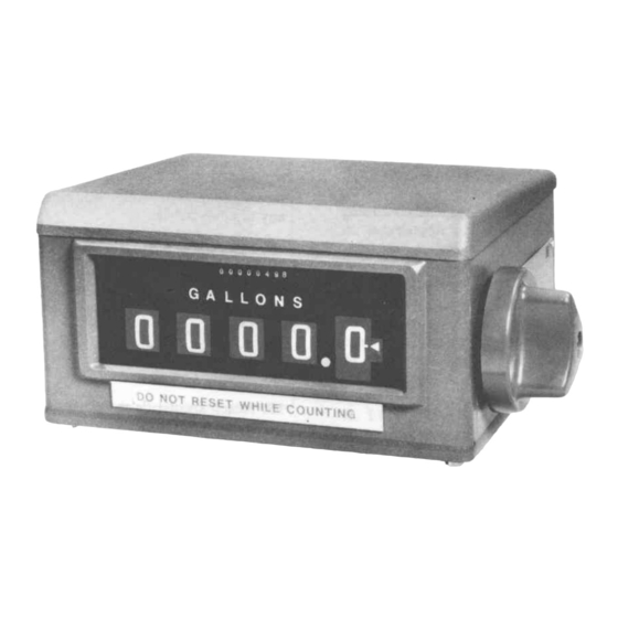
Figure 1. External View of Series 7887 Meter Register. 2. SERIES 7887 DESCRIPTION 2.2. SPECIFICATIONS. 2.1. GENERAL. Specifications listed are standard unless 1. Physical. The Series 7887 Meter Register, otherwise noted. Option al features are Figure l, displays a running account, final total available at additional cost. - Page 5 Figure 2. internal View of Series 7887 Meter Register Figure 3. Mounting Dimension Edition du 24/02/09 / 17 U508218-e Revision : 2...
-
Page 6: Periodic Inspection
3. PERIODIC INSPECTION b. Output bevel gear on gear plate with the bevel 3.1. GENERAL. drive gear on drive shaft. c. 57 tooth gear on clutch assembly with gear on The Meter Register is fully lubricated and properly right wheel assembly. adjusted manufacture. - Page 7 Figure 4. Lubrification Points Edition du 24/02/09 / 17 U508218-e Revision : 2...
-
Page 8: Troubleshooting
3.6. TROUBLESHOOTING. Table 1 is used to assist in locating problems and making repairs and corrections. In some problems, similar defects can be produced by several causes of an entirely different nature. Cause of the trouble must be determined and the correction made. Table 1. -
Page 9: Disassembly And Assembly
4. DISASSEMBLY AND ASSEMBLY 4.1. GENERAL. 1. If present, remove the retaining ring securing the reset idler gear to the reset idler When disassembling the meter register, be gear shaft. extremely careful not to lose or intermix any of the washers round on the shafts. By doing so, 2. - Page 10 4. Clutch Shaft Group Removal. Note: If the inoperable totalizer has a small bevel a. Remove retaining ring and washers securing gear (approx. 11/32 inch dia.) on the drive shaft, the clutch shaft group to the left-hand Bide plate. replace the bracket group on the left side frame as See Figure 6.
-
Page 11: Individual Parts Replacement
4.3. INDIVIDUAL PARTS REPLACEMENT 1. Clutch Shaft Parts Replacement. See Figure 10. a. Totalizer and Drive Bevel Gears. (1) Drift out pin securing gear to shaft. (2) Remove gear. (3) Remove retaining rings and washers that position drive gear. Do not change the order of the rings and washers. -
Page 12: Installation Of Major Groups
4.4. INSTALLATION OF MAJOR GROUPS Prior installing each shaft, lubricate Paragraph 5 in Section 3. During assembly, do not intermix washers from one shaft to another. 1. Wheel Group Installation. a. If not present, install a 0.030 inch thick washer over the end of the wheel group shaft opposite the cam. - Page 13 screws. For adjustment of bevel gear drive, 6. Right-hand Side Plate Installation sec Paragraph E, 5. Hold meter register assembly as shown in Figure 20 and place a rubber band around 8. Spring Installation. the assembly to hold it together. Be sure the pin in the reset lever group remains See Figure 21 for identification of springs.
- Page 14 e. Install washers and detent lever group onto shaft and engage shutter with tab on detent lever. f. Push shaft through the right-hand side plate and secure with washer and retaining ring. g. Secure detent lever group into position with retaining rings.
- Page 15 Figure 26. End Play Limits Edition du 24/02/09 / 17 U508218-e Revision : 2...
-
Page 16: Final Checks And Adjustments
4.5. FINAL CHECKS AND ADJUSTMENTS 1. End Play Check: Check end play (back and forth motion) of shafts and parts as follows: For proper measurement, the meter register must be installed in the TD-42383 mounting fixture, Figure 24, to constrain the frame into the same position that it is when installed in the housing. -
Page 17: Operational Check
4.6. OPERATIONAL CHECK. Before returning the meter register to normal service, check that it operates properly as follows: Rotate the input bevel gear and see that the totalizer and individual delivery wheels are driven and that they record the same amount.. There should be no binding or drag. 2.
Need help?
Do you have a question about the 7887 Series and is the answer not in the manual?
Questions and answers