Table of Contents
Advertisement
Quick Links
CENTURY_T4000TW_V3.1
T
4
0
0
0
F
u
l
T
4
0
0
0
F
u
B
a
r
i
a
t
r
i
c
H
o
B
a
r
i
a
t
r
i
c
H
o
I
n
s
t
a
l
l
a
t
i
o
n
a
I
n
s
t
a
l
l
a
t
i
o
n
a
I
n
s
t
r
u
I
n
s
t
r
u
l
E
l
e
c
t
r
i
c
l
l
E
l
e
c
t
r
i
c
m
e
c
a
r
e
B
e
d
m
e
c
a
r
e
B
e
d
n
d
O
p
e
r
a
t
i
n
g
n
d
O
p
e
r
a
t
i
n
g
c
t
i
o
n
s
c
t
i
o
n
s
Advertisement
Table of Contents

Related Manuals for Tuffcare T4000


Summary of Contents for Tuffcare T4000
- Page 1 CENTURY_T4000TW_V3.1...
-
Page 2: Table Of Contents
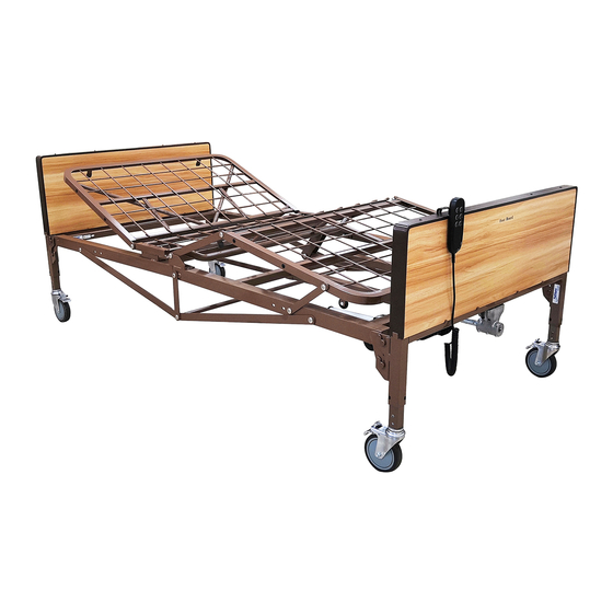
600 lbs. It is specially engineered and designed for Alzheimer residents or others with chronic impairments which will reduce their Emergency Hand Crank degree of independence in their daily activities. The T4000 is a Junction Box Functions fully electric adjustable bed. The bed height, head, and foot angle... -
Page 3: Safety Precautions
Follow the Safety Warnings and Operating Instructions in the service/User’s brackets. manual. Contact your dealer or visit WWW.TUFFCARE.COM. • Be sure that bed side rails are properly attached on the main frame 2. -
Page 4: Product Specifications
PRODUCT SPECIFICATION MAIN COMPONENTS PRODUCT SPECIFICATION MAIN COMPONENTS Control Operation: Tri DC Motors System with 4 Function Pendant Bed Fabric Height: 18 - 25 inches Sleep Surface: 42 x 80 inches, Overall Length: 88 inches Overall Width: 42 inches w/o Side Rail, 48 inches w/Rail Overall Height (with Side Rail Up): 34 - 41 inches Maximum Back Angle to Horizontal: 65 degrees Maximum Knee Angle to Horizontal: 43 degrees... -
Page 5: Assembly
ASSEMBLY ASSEMBLY WARNING Heavy object team lift required. Use only Tuffcare parts to complete this bed assembly. ASSEMBLING THE HEAD/FOOT MAIN FRAME TOGETHER Hardware Pack 2 pcs of Flanged Socket Head Cap Screws 6 pcs of Flanged Socket Head Cap Screws... - Page 6 1b. Pick up the head frame (B) and at a 75 degree angle fit the head frame hooks onto the two shoulder rivets on the side rail of the foot frame. 1c. Slowly rotate the head frame until it is lined up with the foot frame in a straight line.
- Page 7 1d. After securing the head and foot frames together, slowly lower 2a. The next step is to fit the bed frame onto the headboard the frame to the floor with spring section of the frames facing up. and footboard. All head boards are taller than the foot boards. Caution: This step requires two people, do not attempt to do the installation alone.
- Page 8 3a. The longer, head frame drive tube, needs to be attached to the head section’s left plates. The extention tube with the double hole side should face the headframe and the single hole side goes over the drive shaft. 3c. Lift the other side of the drive shaft extention tube, slide it between the two lift plates.
- Page 9 Connect the spring loaded end of the long drive shaft 5a. For the bariatrics T4000 heavy duty bed a reinforcement onto the gear boxes's shaft on the headboard end. Pull shaft side bracket is to be mounted on both side of the frame.
-
Page 10: Half Bed Side Rails
5c. Connect the crossing bar D to supporting bar at both sides of the connection points of A and B. Repeat on other ASSEMBLING SWING-DOWN HALF BED SIDE RAILS side then re-secure all of the socket head cap screws. Note: Secure the caster locks in place to prevent the bed from moving. -
Page 11: Operation
OPERATION OPERATION PREPARING THE BED FOR USE 1. Make sure all electronic components are well connected, and all wires are clear from moving parts. 2. Check and tighten all hardware BEFORE use. WARNING The user must be assessed by a qualified professional. Thoroughly read and fully understand the instructions in this Owner’s Manual. -
Page 12: Raising/Lowering The Bed
RAISING/LOWERING THE BED WARNING DO NOT exceed the maximum weight limit of 600 lbs for the bed. WARNING Operation of this device with any part of the body in the frame can result in injury. Do not place your arms or head in the frame during operation. -
Page 13: Junction Box Functions
Note: There is only one upper locking position for Tuffcare bed side rails. 1. Hand Pendant/Control Panel 2. Head Motor 3. Foot Motor 4. Hi-Low Motor Press Release Trigger 5. -
Page 14: Maintenance
Tuffcare satisfac- ® tion to be defective, such product will be repaired or replaced at Tuffcare DETECTING WEAR AND DAMAGE option. • Check monthly that all screws are tight and have not ®...
Need help?
Do you have a question about the T4000 and is the answer not in the manual?
Questions and answers