
Related Manuals for Icom IC-F1020


Summary of Contents for Icom IC-F1020
- Page 1 INSTRUCTION MANUAL VHF LAND MOBILE RADIO iC-f1020 UHF LAND MOBILE RADIO iC-f2020 This device complies with Part 15 of the FCC Rules. Operation is subject to the condition that this device does not cause harmful interference.
-
Page 2: Important
READ ALL INSTRUCTIONS pletely before using the transceiver. SAVE THIS INSTRUCTION MANUAL — instruction manual contains important operating instructions for the IC-F1020 and IC-F2020 LMR TRANSCEIVERS. EXPLICIT DEFINITIONS The following explicit definitions apply to this manual. WORD Personal injury, fire hazard or electric shock RWARNING may occur. -
Page 3: Table Of Contents
For U.S.A. only CAUTION: Changes or modifications to this transceiver, not expressly approved by Icom Inc., could void your authority to operate this transceiver under FCC regulations. TABLE OF CONTENTS IMPORTANT ... i EXPLICIT DEFINITIONS ... i CAUTIONS ... -
Page 4: Panel Description
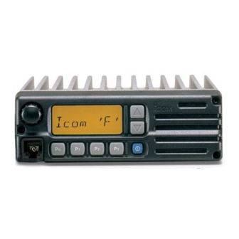
PANEL DESCRIPTION Front panel VOLUME CONTROL MICROPHONE CONNECTOR FUNCTION DISPLAY PROGRAMMABLE FUNCTION KEYS PROGRAMMABLE POWER SWITCH FUNCTION KEYS SPEAKER... -
Page 5: Programmable Function Keys
VOLUME CONTROL Adjusts the audio output level. • Minimum audio level (when setting control at maximum counterclockwise) is pre-programmed. POWER SWITCH Turns the power ON and OFF. • The following functions are available at power ON as op- tions: • Automatic scan start •... - Page 6 PANEL DESCRIPTION BANK SELECT KEY Sets the [ ] and [ CH UP BK S keys. • Push this key, then push the [ the desired bank. • When the optional UT-105 is installed, push one or more times to select a channel bank for conventional channels or SmarTrunk II™...
- Page 7 TALK AROUND KEY Turns the talk around function ON and OFF. • The talk around function equalizes the transmit frequency to the receive frequency for mobile-to-mobile communica- tion. EMERGENCY KEY Push and hold the key to transmit an emergency call. EMER •...
-
Page 8: Function Display
PANEL DESCRIPTION Function display BUSY INDICATOR Appears while the channel is busy. TRANSMIT INDICATOR Appears while transmitting. BANK NUMBER READOUT Appears for the ‘Bank’ type and 180 channel type only. Shows the selected bank number or a hundred digit to show more than 100 channels. BELL INDICATOR Appears or blinks when the optional 2-tone call is received. -
Page 9: Operation
Turning power ON q Push [K ] to turn the power ON. • A power-up alert tone sounds for about 1 sec. and an opening mes- sage may appears. w If the transceiver is programmed for start up passcode, input digit codes as directed by your sys- tem operator. -
Page 10: Receiving And Transmitting
OPERATION Receiving and transmitting RECEIVING: q Push [K ] to turn the power ON. w Push [ ] or [ ] to select a channel. CH UP CH DN e When receiving a signal, adjust the volume to a comfort- able listening level. -
Page 11: D Dtmf Transmission
D DTMF transmission If the transceiver has [ ] key, the automatic DTMF trans- DTMF mission function is available. Up to 7 DTMF channels may be available. q Push [ ] to select the display DTMF as at right. w Push [ ] or [ ] to select CH UP... -
Page 12: Connection And Installation
CONNECTION AND INSTALLATION Rear panel and connection fi Optional cable (OPC-617) ⁄ › ‹ Supplied DC power cable Optional speaker (SP-10) Antenna ¤ red: , black: . -
Page 13: Unpacking
⁄ ANTENNA CONNECTOR Connects to an antenna. Ask your dealer about antenna selection and best installation location. ¤ MICROPHONE HANGER Connect the supplied microphone hanger to the vehicle’s ground for hanger function when hanging or releasing the microphone. ‹ DC POWER RECEPTACLE Connects to a 12 V DC battery. -
Page 14: Mounting
CONNECTION AND INSTALLATION Mounting Flat washer Spring washer When using self-tapping screws Separation q Separate the front panel from the transceiver main unit using an allen-wrench (1/32 in). w Connect the optional separation cable to the both front and main unit attachments (fig. 1 and 2). •... -
Page 15: Optional Ut-105 Installation
CONNECTION AND INSTALLATION Optional UT-105 installation The optional UT-105 provides SmarTrunk II™ functions. In- stall the unit as follows: q Turn power OFF, then disconnect the DC power cable. w Unscrew the 4 screws, then remove the bottom cover. e Install the unit as shown in the diagram below. r Replace the bottom cover and screws, then the DC power cable. -
Page 16: Optional Smartrunk Ii™ Operation
OPTIONAL SmarTrunk II™ OPERATION SmarTrunk II™ and conventional modes This transceiver meets to SmarTrunk II™ functions. The optional UT-105 allows communication in conventional channels or SmarTrunk II™ channels. Select a channel bank for SmarTrunk II™ before trunking operation. • Push [ ] or [ ] one or more times to select a chan- BK UP... - Page 17 D Terminating a call After completing a call, push [#] to disconnect (hang up). IMPORTANT: If one person in the conversation terminates a call, all participants will be cut off. D Last number redial Push [M], [M] to automatically redial the last number called. •...
- Page 18 OPTIONAL SmarTrunk II™ OPERATION D Clear channel alerting If all channels are busy, the transceiver automatically begins searching for an open channel and beeps every ten seconds. When two short beeps (low-pitched, then high-pitched) are heard, a channel is available. Push [M], [M] immediately to re- dial the last number.
-
Page 19: Options
EXTERNAL SPEAKERS SP-5 Large speaker for good audio quality. Input impedance: 4 Max. input power: 5 W SP-10 Compact and easy-to-install. Input impedance: 4 Max. input power: 5 W RMK-1 SEPARATION KIT and SEPARATION CABLE Allows you for separate installation of the transceiver main unit and front panel for easy installation and good operation convenience. - Page 20 A-5441S-1US Printed in Japan 6-9-16 Kamihigashi, Hirano-ku, Osaka 547 Japan Copyright © 1995 by Icom Inc.
Need help?
Do you have a question about the IC-F1020 and is the answer not in the manual?
Questions and answers
Здравствуйте, работаю на производстве очистные сооружения от водоканала. У нас есть стационарная радиостанция ICOM ic-f1020-2.к сожалению ей уже лет 20. Но она работоспособная, только её забросили. Но вопрос в другом. Сейчас снова возобновили спрос к ней. А лет 5 назад о ней забыли и не обслуживали. Выносная антена расположенная на мачте 2,5 метров упала, рассыпался изолятор с креплением к трубе стойки. Осталось от антенны только штырь, остальное непригодно. У меня вопрос, где я могу заказать необходимый элемент антенны, чтобы привести радиостанцию в рабочий вид