Table of Contents
Advertisement
Quick Links
Advertisement
Table of Contents

Related Manuals for Minka WESTFORD


Summary of Contents for Minka WESTFORD
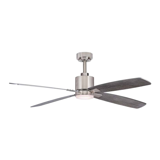
- Page 1 WESTFORD READ AND SAVE ALL INSTRUCTIONS INSTRUCTION MANUAL WARRANTY CERTIFICATE...
- Page 2 © 2019 Minka Lighting, Inc. Manual design and all elements of manual design are protected by U.S. Federal and/or State Law, including Patent, Trademark and/or Copyright laws. 1151 W. Bradford Court, Corona, CA 92882 For Customer Assistance Call: 1-800-307-3267...
-
Page 3: Table Of Contents
WARRANTY The Minka Ceiling Fan Co. warranty is for one (1) year from the date of purchase from an authorized Minka dealer. This warranty is only valid to the original purchaser or user against all defects in material and workmanship (light bulbs excluded) for one (1) full year. -
Page 4: Safety Rules
SAFETY RULES 1. To reduce the risk of electric shock, ensure electricity has been turned off at the circuit breaker or fuse box before beginning. 2. All wiring must be in accordance with the National Electrical Code “ANSI/NFPA 70-1999” and local electrical codes. Electrical installation should be performed by a quali ed licensed electrician. -
Page 5: Package Contents
PACKAGE CONTENTS Unpack your fan and check the contents. You should have the following items: 1. Hanger bracket A.Mounting hardware: 2. Standard downrod assembly (6”) 10#1x 1.5” Woody screws(2 pcs) 3. Canopy 3#d5D19 1mm Washer (2 pcs) 4. Canopy cover 8#-32 3/4”Electrical box screws (2 pcs) 5. -
Page 6: Installing The Fan
You may need a longer downrod to maintain proper blade clearance when installing on a steep, sloped ceiling. Longer downrods are available from your Minka Ceiling Fan Co. dealer. in Fig. 4 (available at your Minka Ceiling Fan Co. dealer). -
Page 7: Hanging The Fan-Standard Ceiling Mounting
The use of other parts, hardware or components not supplied by Minka Ceiling Fan Co. with the fan will void the Minka Warranty. to turn off the power. Follow the steps below to hang your fan properly: Step 1. -
Page 8: Electrical Connections
ELECTRICAL CONNECTIONS To avoid possible electrical shock be sure electricity is turned off at the main fuse or breaker box before wiring. Step 1. Motor to House Supply Wires Electrical Connections: Connect the WHITE wire (Neutral) from the outlet box to the WHITE wire marked "AC in N"... -
Page 9: Finishing The Installation
FINISHING THE INSTALLATION STANDARD CEILING MOUNTING Step 1. Remove 1 of the 2 screws from the bottom of the hanger bracket and loosen the other one half a turn from the screw head. Step 2. Slide the canopy up towards the hunger bracket and place the key hole on the canopy over the screw on the hanger bracket turn canopy until it locks in place at the narrow section of the key holes. -
Page 10: Attaching The Fan Blades
ATTACHING THE FAN BLADES Line up the screw holes on blade holder and blade. Tighten the assembly from the blade holder with 3 sets of screws. Repeat the same step for all blades as shown in (Figure 13). Line up the holes of blade holder set and motor holes. for customer to select from when installing. -
Page 11: Operating The Remote Control
OPERATING THE REMOTE CONTROL / WALL CONTROL Remote Control only: Install a A23 12 volt battery (included). To prevent damage to transmitter remove the battery if not used for long periods of time. Your DC brushless motor is equipped with a self learning frequency function remote control. Restore power to ceiling fan and test the transmitter as below for proper operation: A. - Page 12 OPERATING THE REMOTE CONTROL / WALL CONTROL Note: The auto learning function will only mandate within 60 seconds when Fig. 15 turning the fan's AC power ON. 1. Select desired frequency from the back of transmitter. 2. Press the transmitter's “Off” button, and hold the “Off” button for over 10 seconds.
- Page 13 OPERATING THE REMOTE CONTROL / WALL CONTROL WINTER OPERATION SUMMER OPERATION Fig. 16 Fig. 17 Speed settings for warm or cold weather depend on factors such as room size, ceiling height and number of fans. NOTE: to change the direction of the rotation of the blades the fan must be in operation mode. Warm Weather (forward) A DOWNWARD airflow creates a cooling effect as shown in Figure 16.
-
Page 14: Care Of Your Fan
CARE OF YOUR FAN Here are some suggestions to help maintain your fan. 1. Because of the fan's natural movement some connections may become loose. Check the support connections, brackets and blade attachments twice a year. Make sure they are secure. (It is not necessary to remove fan from the ceiling). -
Page 15: Troubleshooting
TROUBLESHOOTING SYMPTOM SOLUTION Fan will not start Check to make sure the wall switch is turned on. Check circuit fuses or breakers. Caution! Make sure the power is turned off before performing the following steps. Remove canopy and check wire connections. Check wall control transmitter connections (if applicable). -
Page 16: Specifications
SPECIFICATIONS Fan Size Speed Volts Amps Watts N.W. G.W. C.F. 0.05 3.39 6.25 7.30 1.369 54” Medium 0.23 16.55 High 0.48 38.41 These are typical readings. Your actual fan may vary. They do not include amps and wattage used by the light(s). PERFORMANCE AND ENERGY INFORMATION 4,805 1151 W.
Need help?
Do you have a question about the WESTFORD and is the answer not in the manual?
Questions and answers