Table of Contents
Advertisement
Quick Links
Advertisement
Table of Contents

Related Manuals for Cirs MRIdian Phantom


Summary of Contents for Cirs MRIdian Phantom
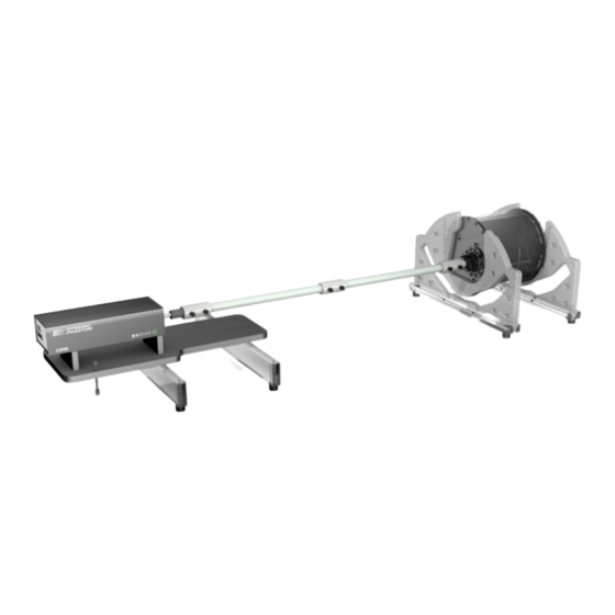
- Page 1 Motion Phantom for MRI Automatic Tracking and Gating USER GUIDE...
-
Page 2: Table Of Contents
Table of Content Overview…………………………………………………………………...2 Description of Phantom…………………………………….…………...2 Specifications …….……………………………………………………..3 Use of Phantom…………………………………………………………...4 A. Unpacking Instructions …………..…………………………4 B. Assembly Instructions ….…….…..…………………………8 C. Oscilloscope Connection….……..………………………13 D. Repacking Instructions …………..………………...………17 Care and Handling…………………………………………....19 Warranty………..…………………………………………....20... -
Page 3: Overview
MRI signal generating Body with static non-deformable targets dosimetry enabled for all targets and OARs. ** Other ion chambers are available. Refer to CIRS cavity codes at www.cirsinc.com/support for corresponding CV number. MRI signal generating Moving Rod with one dosimetry non- deformable target and non-dosimetry and non-deformable targets. -
Page 4: Specifications
Dimensions: Ø254mm x 236mm (Gel Volume ~Ø229.3mm x 220mm) Weight: ≈30 lb. Materials: Body Housing – Acrylic; Body and Body targets – CIRS proprietary gels MRI signal generating Moving Rod Dimensions: Ø63mm x 290mm ( (Gel Volume ~Ø57mm x 254mm) Weight: ≈4 lb. -
Page 5: Use Of Phantom
Use of the Phantom A. Unpacking Instructions Before you open the case check the three Drop ‘N’ Tell indicators on the right side of the case. (Drop ‘N’ Tell shipping damage indicator shows when a case has been dropped in transit and contains potential damaged goods. The sensor displays a red arrow when applied before shipping. - Page 6 Remove MRI Body/Torso Coils supports and set them aside. Pay attention to the foam trays that accommodate these parts as they are fragile. Remove cables and accessories bags from case and set them aside. Remove MRI Moving Rod and set it aside.
- Page 7 Pull base and the actuator assembly from case and set it aside. Remove Motion Controller box from case and then MRI Body Carrying Handle, which is shipped inside of one of the removal cutout of the MRI Body.
- Page 8 Carefully take the MRI Body out from the case and set it aside in a horizontal position laying it on the straight edges of the body’s ends. Remove the remaining hardware from the case and set it aside.
-
Page 9: Assembly Instructions
B. Assembly Instructions Assemble the MRI Body/Viewray Torso Coils supports and MRI Body crossbars using the alignment pins and corresponding holes (circled in blue) and secure in place with the black ½-13 hex nylon screws. Pair the MRI Body/Viewray Torso Coils support with the corresponding MRI Body crossbar, which can be identified by their labels (circled in red). - Page 10 After indexing the two MRI Body/Viewray Torso Coils support - MRI Body crossbar subassemblies to the Viewray couch ( following the naming convention explained before) place the MRI Body between them as shown above. Make sure the body slides inside the two supports and is guided by the walls of the recess pockets so that it locks on the flat faces of the MRI Body’s ends (see below).
- Page 11 To place the MRI Body on the support use the handle and the straps like shown below (make sure the body do no slips from the straps; carry the body as much as possible in a horizontal position with the straps/handle position in a vertical line/plane with the body’s top laser marks).
- Page 12 Connect the shafts together and to the actuator push rod following the sequence from the above pictorials. The recommended procedure is: Identify the top connector bridge (white nylon pieces) with un-threaded large holes (pictorial A) and align the holes of shafts/Absylux connectors with the conical posts of the said bridge (pictorial B).
- Page 13 Note: If there is a need to remove the bridge connectors and they seem to be locked on the shafts use the thumb screws to push against (by screwing them in the outer treaded holes) the shaft, which will un-lock them (see below). For proper alignment of actuator with MRI Moving Rod follow the assembly steps shown above.
-
Page 14: Oscilloscope Connection
C. Oscilloscope Connection The phantom is equipped with a special feature that allows the end user to check whether there is latency between the position of the MRI moving target and the release of the beam based on MRI imaging of the this target. To accomplish this task the phantom is equipped with: An assembly containing two optical switches, which is housed inside of the main linear actuator of the phantom. - Page 15 Cable that allows analyzing two signals at once, on channel 1 and 2 of an oscilloscope respectively. To do adjustments to the signal that is provided by the optical switches and to analyze them on an oscilloscope follow the following steps:...
- Page 16 Open the cover of the actuator box by unscrewing the aluminum thumb screws (see above) and remove it. Unscrew the Optical switch fixation screw of the two inner Optical Switches and adjust the distance between them according to your research study. Use the Adjustment Square to align the Optical Switches at 90º...
- Page 17 Note: The position of the outer two Optical Switches is not adjustable. Do not unscrew their fixation screws. These two Optical Switches are used for safety limits of the travel of the linear motion and for the homing sequence. 3. Close the cover of the actuator box by hand tightening the aluminum thumb screws.
-
Page 18: Repacking Instructions
Note: The short DB9 to Oscilloscope cable has its oscilloscope labeled as SUP for the Optical Switch that is toward the linear motor and INF for that is toward the back of the actuator due to the fact that the Phantom is designed for “Supine Head First”. - Page 19 Cap Screw 1/2"-13 Thread, 1-1/2" Length, Black 6 x 1/4-20 1.5" long Nylon Thumb Screw, 1 x 1/4-20 1" long Nylon Thumb Screw (1) CIRS Motion Control Software USB Drive (1) Motion Controller Power cord (1) Cable Kit, CAT5e - 75 feet with USB 3.0 Gigabit...
-
Page 20: Care And Handling
(2) 2 amp fuses Included with Model 008V (1) Extra fasteners pack (min quantity in brackets): Nylon Thumb Screw ¼-20x1.5” (6); Nylon Thumb Screw ¼-20x1” (2); Nylon Pan Screw ¼-20x5/8” (2+2 with O- rings); Nylon Pan Screw 10-24x3/4” (8); Nylon Pan Screw 10-24x1”... -
Page 21: Warranty
Long Term Storage: For longest life, the MRI Body and Moving Rod should be stored at room temperature. These phantom parts SHOULD NOT be subjected to freezing or boiling conditions such as those encountered in the trunk of a car during a South Dakota winter or Arizona summer.
Need help?
Do you have a question about the MRIdian Phantom and is the answer not in the manual?
Questions and answers